
Ampro Little Board Plus SBC, before placement in fat box.
The classic 8080 compatible SBC is the Intel SDK-85. It's a great small system that has started countless numbers of engineers on their path to digital electronics greatness. It comes with a nice keyboard, a decent display, a nice monitor program, and an 8085 core system that's ready to go for plenty of I/O. They're still very popular, which means they are pretty expensive--at least for someone who just wants a small system to use for fun. The PCB is a bit large for portability, as well. But there is excellent support for it, plenty of software and a number of books.
Since I couldn't see paying for an SDK-85 when I've got parts drawers with 8085s and Z-80s in them, I decided to build my own system. Even though I like the advancements the Z-80 added to the 8080, I decided to go with an 8085 as the heart of my home-made system. To some degree, it was the retro thing striking. The Z-80 feels a bit "new" (actually it and the 8085 came out about the same time, but I didn't get a chance to use a Z-80 myself in my own designs until a few years after putting together a couple 8085s.) If I had had an 8080A, I would not have used it. I'm not that retro-foolish. It is much more of a pain to build a system around than either an 8085 or a Z-80. I'd rather build an 8088 or 8086 system, to tell the truth, or, rather, a V-20!
So I pulled my newest datecode 8085 out of the drawer and got going.

The simplest possible 8085 microprocessor circuit-a free run circuit.
Since I'm doing the initial build on a logic lab with power built in, I didn't have to worry about a power supply for now. Next was to get the clock circuit sorted out. A crystal oscillator makes that easy. I put its signal through a 7400 to get a push-pull design since I intend to run it up to 6MHz, and the 8080-85 Family manual recommends this for 6MHz and above.
The next step was to drop in the CPU. If I'd had to build a complete core system right off the bat it would have taken longer than one short evening to get something going. And it would have introduced countless opportunities for error, which I am very adept at inadvertently locating. So I built what's called a "free run" circuit. You hardwire in an opcode that doesn't stop or redirect the processor, then it runs through its entire address space when you fire it up. It allows you to make sure you have the clock and CPU control wiring working, at least in a nascent form.
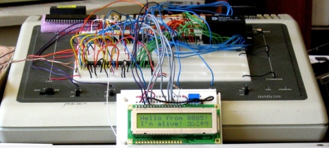
The resistors above are the hardwired instruction. They allow the CPU to put a value on those lines without forming a short to a power rail, then pull the lines to the instruction value when the 8085 is reading it. The instruction is 00, a NOP or no-op in 8080-85 terms. The CPU does nothing and moves on to the next address.
The yellow wires at the top wire some of the address lines to LEDs so I can watch the 8085 step through its address space.
After one fix of an improperly placed wire (/RESET), it worked fine.
Evening 2 had me adding an address latch. Again, moving by baby steps. Evening 3 added an EEPROM with a four byte program:
0000  3E C0        MVI A, 0C0H          ; enable SOD, set it high
0002  30              SIM
0003  76              HLT                        ; stop
Hand assembled and typed into my Xeltek Superpro/L's buffer directly for programming the EEPROM (as are all the programs for my 8085 to date.)
I got that working to demonstrate the successful interface between the 8085 and a memory. I turned up another wiring error while I was at it (address lines A1 and A3 were swapped coming off the latch.)
Next, I was going to add a RAM but decided to replace the EEPROM with a NOVRAM instead. I've got some Dallas DS1225Ys that I pulled off some scrapped SCSI controllers years ago. They're ten years past their expiration date, but most of them are fine. Using a NOVRAM lets me reduce system memory to a single chip. It also sets me up for all sorts of amusing misadventures (like all memory going *poof* if the /RESET circuit isn't rock solid.) Trade-offs are part of the design process. If I get too annoyed with cleaning out system code in interesting ways, I'll add an EPROM once I've got a simple monitor program written.
Next was testing the RAM with a simple program (presented here un-assembled):
MVI L, 0F0H    ; set up memory pointer
MVI H, 1FH
MVI M, 5DH    ; write out some easily recognizable bytes
INX H
MVI M,41H
INX H
MVI M, 52H
INX H
MVI M, 5BH
MVI A, 0C0H  ; show we did something, turn on LED on SOD
SIM
HLT                ; stop
Then i pulled the NOVRAM and read it on my programmer. It showed that the program ran fine, verifying that I'd rewired for the DS1225Y properly. I even got the circuit to stop futzing the RAM up at power-on when I put a pull-up on the RAM's /WE line. ;)
Now I've got switches connected to the interrupt lines on the 8085 to provide me with "interactive input." I wrote a program that blinks the SOD LED a different number of times depending on which interrupt it's servicing.
Next is adding I/O for a keyboard and multidigit LED display. I did consider the idea of using just the interrupt lines for user input. An old telephone rotary dial switch and a little code would do the trick. But then I decided it'd be too noisy, compared to a keypad. And maybe just a wee bit too retro for daily use.
Edit: I've done a complete write-up of thise project at saundby.com. This includes assembly instructions, design notes, project code, and so on.


 Webomator.com: Backward into the