Wednesday, December 21, 2011

KJ6TFT's First QSO, My First QSL

My daughter's call sign showed up in the FCC ULS database today.

First QSO

I sent her out to the driveway with my 2M HT while I sat inside with my Kenwood TS-700A base station. I had a yagi up on the roof, in horizontal orientation so that I could try out SSB, but I figured at a distance of fifty feet or so orientation wouldn't matter much. I'd set the HT to the simplex frequency 147.510, and had been listening in on that frequency on the base station for a while to see if anyone else was using it.

The frequency was clear, my daughter was outside the house a way, I waved through the window to let her know to go ahead. She called me just fine, "AG6HU this is KJ6TFT." It came in clear on the Kenwood, I came back, "KJ6TFT, this is AG6HU. You're coming in five by nine."

"That's great! KJ6TFT."

"Do you want to give me a signal report?"

"Oh, yeah. You're loud and clear. KJ6TFT."

"Thanks. QSL?"

"What's that? KJ6TFT."

"It's confirmation of contact. Do you agree to confirm our contact?"

"Oh. I thought that was QSO. KJ6TFT."

"That's a communication. Like, Q Signal Out. It can be confusing. So, QSL?"

"Yeah, QSL. KJ6TFT."

"Great. Thanks. AG6HU clear."

"KJ6TFT clear."

You can read my daughter's account of her first contact here.

First QSL

After our communication I pulled up GIMP to make a special one-off QSL card for her. I printed it out on 110# cover stock and coated it with a clear fixative. That stiffened it up nicely. Here's my quick and dirty one-off QSL card:

AG6HU Radio to the World (or at least to the driveway.)


Afterward, I let her know that she didn't have to give her call sign on every transmission. I also had a quick look at the Kenwood. The antenna wasn't plugged in at all! Worrying about polarization is pretty meaningless when you're putting out RF from nothing more than an SO-239 plug. Still, we made the contact. But next time I think I'll at least stick a piece of hangar wire into the plug. ;)

Tuesday, December 20, 2011

She Passed the Amateur Radio Test

My oldest daughter, Amaryllis, went to take the Amateur Radio Exam this Saturday. I went along, for moral support and because I already knew the way to the exam site. Plus, she got to study while I drove.

She passed the Technician Class exam handily, and went on to take the General Class exam. She fell short of passing it by a few questions, but did well considering she hadn't studied beyond the Tech question pool and subjects. Maybe she'll want to upgrade this spring, I'm putting together an HF station to deal with the fact my house is in a gully surrounded by 100 foot tall VHF-eating trees. I suspect she'll want more HF privileges once she gets a taste of it.

She's blogged about her experiences here.

I took her up on the roof with me yesterday to put up a trial antenna for 2m SSB. I had her running the antenna analyzer while I made final adjustments to a four-element yagi on a fiberglass pole. She seemed to enjoy being part of the process and talking to me about how the antenna is supposed to work, what the numbers on the analyzer represent, and so on.

Antenna Hijinx

The yagi was a failure (terrain and trees win again), but our time together was good. The Kenwood TS-700A got one side of a nearby conversation on SSB, but it was down in the mud. The static was deafening. Next I'm going to see if turning the yagi to vertical will give me any improvements on FM over the three other antennas I've tried so far. Plus I'm going to see if I can't get a pilot line over a high tree branch with a bow and arrow (blunt tip) to pull up a 2m vertical and possibly a simple HF wire antenna to get started with once I've got an HF rig.

It'll go to the shortwave receiver until then to help me get a better idea of what I can catch here. The shortwave gets plenty of 80m at night, and picks up some 40 and 160m traffic, just with the built-in whip, indoors. It gets some 20m and 10m traffic, with hints of 15m, during the day. I think we're getting some beneficial knife-edge refraction off the surrounding terrain at 80m. I guess there's software to model this, it'd probably be worth my while to look into it before committing to a sizable antenna project.

As to 2m, at some point I'll get a more powerful rig--after I get the HF rig purchased. The Kenwood has no PL, but I'm going to try some FM simplex to see if that works better than SSB. If Amaryllis gets her call in a day or two I can send her out with my 2m HT and a car to see what sort of a pattern and signal strength we can get in and out of here from the nearby area. Plus, once school starts again I want to take a radio into class and do a little demo. Amaryllis can see what sort of signal we can get to the school (if any). Or I'll go if she'd rather run the Kenwood at home. We'll see.

Having a second ham in the house will sure be convenient.

Friday, December 16, 2011

Amateur Radio: A New Hope

After my prior post wondering what I should do to pull together a ham shack for <$1000 or so, I noticed I wasn't getting much feedback either online or off. This is usually a sign I've asked the wrong question. Sure enough, I've gotten a response now that verifies that.

Fortunately I've had a distraction that's kept me from fretting too much.

My oldest daughter has been studying for her own ham radio license.

The First Harmonic Doesn't Fall Far from the Primary

She's been playing with microcontrollers for the past several months, learning the basics of electronics and low level programming. When I talked about some of the things on the amateur radio exam, they sounded familiar to her. I guess I got her interested.

She's been studying for about a month now, in spite of distractions from work and her other hobbies. Tomorrow morning she's going to take the test. A week ago I wasn't sure she'd be ready, her online tests were coming up more fails than passes (the online tests are a really great study tool!) Since then, we've had mini lectures on propagation, capacitors and inductors, and rules & regs. She's also had a chance to focus on her study a lot more this week, and take more tests to see more of the questions. She's scoring much better now, consistently passing the test with 3-5 missed questions. Good enough to drive down to a test tomorrow morning.

Hopefully she'll have a CSCE tomorrow. If not, I'll tell her my stories of how I failed my first attempts at getting my license and reassure her that another test will be available soon. The only way to fail is to stop trying.

My Plan, Revised

To get an HF set-up of the sort I want takes more money than I have now. I started writing down lists of rigs, the necessary bits to get them on the air (power supplies, antenna tuners, etc.) and realized I can afford a single or dual band mobile, not a base station. Kits aren't all that cheap, either, once I look at what I can build without much infrastructure and get something of quality with long term value.

So, 1st step: be patient and build up money for a more realistic station budget--as I learn more.

Step 2: Try some more things to get some QSOs with my 2m FM HT on simplex (like from the parking lot at the store while the wife shops for XMas) plus see if I can get an SSB or CW signal out of my home location with the Kenwood TS-700A 2m rig I've got. Its receiver isn't very sensitive (I think the quartz stones in front of my house convert more signal), but we'll see. Maybe I can adjust that.

I'll also play around with horizontally polarized omnidirectional antennas or put up a beam and reposition it by hand every so often (no rotator yet--something else that'll take money when other things have been dealt with.) I put up a wire yagi last week, but couldn't hear an SSB net that was scheduled with the 700. Maybe I can figure out why this week.

Meanwhile, I'll see what I can log from parking lots with an HT. :)

2 meter band handheld transceiver

Tuesday, December 13, 2011

Best Starter Ham Shack for <$1000?

In my research I've stumbled on a question that elicits a lot of opinions. What's a good starter ham radio rig to buy? There are a lot of answers, and working through the answers requires a more specific question is what I've learned so far. So here goes. Short form first, more background below.

I'm looking for:

  • A fixed base rig to operate off wall power.

  • 80m to 10m, 160m is greatly desired, 6m would be a nice frill.

  • Rig price on the order of $500 or so, depending on extras:

  • With all the bits--filters, power supply, feedline, key and/or keyer, mike, antenna tuner, etc. I'd like to bring the bundle cost in at about $800, up to as much as $1000 once the last insulator, connector, and screw is in place.

  • Furniture and basic facilities like light, heat, and air isn't included in the cost,

  • but a lot of little things like the antenna feedthrough, cable, switches, and connectors are, which is why I'd like the big pieces to come in around $800.

  • I'd be willing to go higher if I felt really secure that I'm investing in something I'm likely to get much more or better use out of, but I'd still be capped about about $1200-1400 for now, anything more would have to wait.


Detail
My present home location appears to be best for HF work, so that's where I'm going to concentrate for now. I expect to pick up a good enough 2m rig to be able to hit the local repeaters for the sake of keeping in touch with the local hams, but VHF isn't where I'm looking to do my regular operating. This rig will be for a fixed station operated when the power is on, so portability and power conserving reception is not a factor, especially when weighed against receiver sensitivity and other such factors.

Antenna
I have plenty of space for an antenna, but I'm not expecting to start with anything sophisticated in the way of masts--trees will probably be my initial supports, or a small mast off the top of my garage. I have no fixed idea as to whether to build or buy my first HF antenna. I'd like it to be multiband. I'll look at ideas from stringing up a center-fed 12ga wire dipole to a quad band yagi with a rotator.

For the initial antenna set-up, I'm willing to compromise with the expectation of getting more or better later. But I want to start with something good enough that I'm not cut off at the knees while I'm still getting a feel for what I'm up to. It's worth noting that I have an MFJ-259B antenna analyzer on hand.

Operations
I don't know what my primary mode is going to be yet. I want to work CW and SSB. I'd like a rig that'll let me dabble a bit, so I'd prefer it to not have any major weaknesses even if it's, say, the greatest CW rig ever built. I'd like to try some digital modes, some SSTV, and some ATV.

The extra equipment for these other modes isn't included in the cost, I just want to be clear that I'd like a rig that can do it at least well enough to get started and figure out if I want to put more money into it later. So a rig that can handle the duty cycle these modes impose is probably going to be necessary.

QRP isn't where I'm looking to start here. I've already got my site working against me, and I really don't know what it's going to take in the way of power to work from here. So the rig should probably be about 100W or more until I know--unless you can tell me better.

I'm expecting to build my own QRP equipment later. The rig I'm looking at getting should be a solid workaday affair, I'll have fun building watch battery wonders later. ;)

QRU?
So, fellow hams, where does that put me? An old FT-450 or TS-480? Or one of the new "shack in a box" rigs with some extras? Would I be better off springing for a good beam and rotator now, or will a wire dipole hung from some spruce trees get me enough QSOs to keep me going until the money reserves and operating experience build up?

Your opinions are welcome. I know that you can't tell me exactly what I should get. I'm just looking for opinions more seasoned than my own wild guesses. I just want to get an idea to start out reasonably effectively, while keeping the spending down enough that it won't ruin the hobby even if nothing I do works out as planned. ;)

Saturday, December 10, 2011

New Ham Progress: Working Toward a Working Station

It's been 3 weeks since I got my CSCE for my amateur radio license, two and a half weeks since my license appeared in the FCC database. Each day I've been working to make material progress to set up a station and start operating. So far I'm not fully "on the air", though I've made a lot of progress.

my certificate of successful completion of exam for all three amateur radio tests
I passed the tests! Now what?

Getting a station up and running could happen quickly through purchasing a "shack in a box" transceiver with antenna, feedline, and accessories and setting them up. The set-up of the antenna, feedline feed-through, and learning to operate the transceiver and the aavailable ba would be no small feat in and of itself. But I'm taking a bit slower path.

As I progress, I'm learning a bit more about what I've got to work with--hopefully leading to better decisions when it does come time to lay out for equipment.

Starting Point
While I had a ham license before, I did very little with it. I had a mobile 2m rig in my car that I used on the local repeater. I helped at a local long-disstance charity run. I hoped for more, but that's all I did. I never really built up a station or even learned the routine on simplex operations.

Since then I had a friend give me a Kenwood TS-700A all-mode 2m rig. I can't locate my old IC-230 mobile rig, it's around somewhere, but I haven't found it yet. No matter, it's not much use to me in the present day. The 700A is a decent rig, but the receiver is pretty insensitive. Even if I just use it for SSB and CW it'll need a preamp and probably a power amp. Because of my location.

I've moved since my last time around with ham radio. I used to live in a fine location, now I live in a place where I'm poorly situated and surrounded by thick VHF-eating trees.

I also turned up about 60 feet of RG-8, a couple of awful little straight keys, and some other odds and ends.

Moving Forward
VHF will be important to staying in touch with local hams, but I need some tools that can deal with my location. For less than the price of a preamp/amp combo for the Kenwood TS-700A I can get a mid power, more flexible, more sensitive current-production 2m or multiband VHF/UHF rig. I still expect to have fun with the TS-700A down the road, but for normal workaday comms, a new 50-75W 2m rig would make more sense.

I did buy a little Yaesu FT-250R handheld, but it can't hit the local repeaters even with an external ground plane antenna mounted about 40' above grade. I built a simple yagi for testing, too, but I'm between repeaters so I'd like to use an omnidirectional antenna for general FM. The yagi was built to see if I could manage any SSB here. So far no luck but this is still work in progress.

More Site Assessment
To get a better idea of what might work here, I picked up a Grundig G3 shortwave receiver last night. I've been tuning around through the ham bands to see what comes in. MF/HF is definitely more promising here than VHF. It seems (so far) that 160m and 80m will be good here at night, with 20m being a decent daytime band. The jury is still out on the other HF bands. I need to put in an external antenna for the G3, so far I've just used the little whip on top.

Build or Buy
While I expect to build equipment in the future, I'm also expecting to establish the station with solid purchased equipment. Whether new or old I'm not sure yet, I have to spend more time with other local hams to find out my options. But prebuilt equipment will allow me to operate while I'm building other rigs--QRP rigs or whatever--plus it'll act as test and calibration tooling for my scratchbuilds.

From what I can see so far, I think I'd be just as happy at this point with solid equipment from any time in the past 25 years or so as I would with new stuff. For example, something like the late-80s Kenwood TS-440S or Icom IC-765 look like they'd still do fine today for my present needs. Maybe--I'm still guessing at this point. So I need to learn more and get some idea of price differentials and all that.

Meanwhile...my ground rod is in, I'm clearing an area for my station that'll get its own AC/heater unit and antenna cable feed-through. I'm experimenting with antennas and mast mounting positions and otherwise trying to make it so that when I do have equipment, I'm prepared to do something at least somewhat effective with it.

Tuesday, December 6, 2011

A Neat Modern Retro Computer: The New Elf II

My first computer was a version of the COSMAC Elf computer. It was a simple little computer, costing about $100 in 1976-77. The joy of it was that is was a real computer, and yet it was direct enough in its design philosophy that every single thing about it was understandable and controllable.

I wasn't the only one enchanted by this small computer system, or to have it as a first computer.

Marc Bertrand has built a new, modern version of the Elf computer, visible at his web page. It's not only got the original video interface of the Elf II, but a nice LCD display driven by a PIC microcontroller. It has heaps of I/O ability through several interfaces, nicely controlled by some Altera programmable logic.

Have a look, it's a sweet little system with a layout very reminiscent of the original Elf II computer.

This isn't it, but it's a little test circuit for the 1802 microprocessor used in Elf systems that makes a nice LED blinky:
RCA 1802 test circuit that happens to make a very nice little LRD blinky
A simple test circuit for the RCA 1802 processor used in the Elf computers

Monday, November 28, 2011

CNC Enclosure: A Home for My MicroCarve A4

I originally set up my microCarve A4 on my workbench as I got the various bits and pieces put together and checked out. This was a convenient place to do the work at that time, but once everything was working, there were two significant problems:
  • It was in the open air. Sawdust and plastic chips were flying everywhere.

  • I wanted my workbench back for other projects!

So it was time to take time off from making cool CNC projects and time to make an enclosure. I spent quite a bit of time thinking through what I wanted. If I put the computer and CNC side by side, it'd take up too much room in the shop. I tried a test arrangement of putting the computer below the CNC, the display above the CNC, and the keyboard and mouse in a drawer just under the tabletop that the CNC sat on. This did my neck no favors at all.

Finally I settled on putting the CNC itself a bit higher, with the computer completely underneath it. This worked out, barely. I had to replace my old CRT monitor with a lower-profile LCD display to get the heights I wanted. It was worth it.

microCarve A4 CNC enclosure, CNC in box on top, computer and controllers on desktop

The desktop is at 26 inches above the floor, the bottom of the CNC is at 48 inches above floor level. It's low enough to handle the tools, parts, and everything else inside as well as keep an eye on the machining as it goes, though an optimum height would probably be a bit lower. A different arrangement of the computer stuff down below could probably allow someone else to make theirs about six inches shorter, if they don't mind looking down at their computer monitor rather than propping it up on the computer cabinet for a comfortable height, as I did.

The desktop holds the computer, monitor, power control center, CNC power supply and Gecko G540 control unit, wireless network hub, keyboard, mouse, and an occasional can of soda (with care).

Another view of the enclosure, and all-in-one roller unit that has the CNC and all of its related electronics in a thirty inch wide unit.

The CNC box has removable panels on the back and sides. The back panel is in three sections, so that a middle section can be taken out for working with stock that's too long for the enclosure. This leaves a panel at the bottom to catch chips, and a top panel to trap some of the high-flying chips. If necessary, one or both of the front doors can be left open with longer pieces, a bottom panel will still cover the lower three inches of the front to trap some of the chips from spilling out. I thought about making sectioned doors, but this project was already getting too complicated.

A look inside the CNC enclosure box at the top of the unit, showing the CNC inside with integral lighting and a power bar for the router spindle.

The top box can lift off of the base with the computer desk. It has small feet that rest inside the uprights on the base and lock it in, as well as a pair of angle brackets that screw into it. Basically the power and control cables that run into the box through the two PVC feed-throughs are are disconnected, the box is lifted off the top of the base (a two-person operation when the CNC is in there!), then set on its feet where ever it suits you.

The base has casters on the bottom, so I can roll it around the shop or out onto the concrete apron outside if I feel like doing my CNC work under the sky. ;)

I plan on adding a vacuum motor and dust trap below the desktop when the urge to take things a step further strikes. I'll cut another feed-through into the box for the vacuum as well as an air intake for the enclosure. Until then I'll just be reaching in with the hose of a nearby canister vacuum to clean things out.

Sunday, November 27, 2011

Amateur Radio Station from the Ground Up

I earned my amateur radio license about a week ago, and it posted in the FCC's data base last Wednesday. My call sign is AG6HU. Vanity call sign, here we come. ;)

Getting on the Air
Still, it's a good enough call sign to get me on the air.

I have two radios at present, both pretty old. One is an Icom IC-230 that I got from a ham in Hayward back in 1986 (another time when I was preparing for a license but didn't get one.) It was my one and only rig when I was KD6KGV. Presently, it's lost in storage some where. I remember coming across it sometime in the past year, so it's not completely lost. When I got it it needed some TLC. A little work and some new crystals and I was in business when I got my first license in 1992.

The other is a rig a friend gave me back when my first license was still active. It had been his father's and he wanted to find a good home for it. Unfortunately, I never got on the air with it. It's a Kenwood TS-700A, vintage 1976 or so. It's a pretty rig, and it was a lot easier to find than the Icom when I went into the garage this last week. However, when I turned it on and started listening to the local repeaters I found that the frequency readout shows a different frequency than the actual frequency of the repeater--by a lot. So I'm afraid to transmit on it until I can recalibrate it. I have the service manual, I just need to pull together some test equipment beyond what I normally use. Back to the garage I go, for more boxes.

Doing What Can Be Done

Meanwhile, I picked up an eight foot ground rod and a clamp at the hardware store, I already had a bag of rock salt on hand. I've got a place picked out in the back of one of my garages for my station set-up, and I was planning on installing the rod just outside. I've got two garages, both attached to the house. The spot I picked has a nice window, and I'll be able to install a combination heater/cooler unit in the wall beneath it.

I decided to use a technique similar to that used by Roger Halstead, K8RI. I had a heavy duty hose with no connector on one end that I slipped over a piece of full conduit (I didn't have a straight enough piece of thin wall tubing on hand). Then I put on a hose clamp, hooked it up to a hose bibb, and I was ready to do some hydromining.

My house is built on rock in a cut that was made to make enough flat space to build the house, run a driveway and so on. So a rock drill and blasting charges would be the most appropriate tools for making a deep hole. However, there's an area around the foundation of the house that was excavated for the foundation. My thought was that I'd put the rod into the area next to the foundation that was excavated, then backfilled.

Unfortunately, I couldn't get more than two feet deep this way. It appears the backfill is primarily what came to hand most easily:rock. So I changed my plans. I'll admit that while I was fighting with the conduit under the eaves of the house the idea of putting down a subsurface wire grid occurred to me, but that would be a weekend-long project at least.

I also have a retaining wall that forms the back wall of my far garage. That puts the ground rod a bit farther from where I want to stack my rigs, but not much further. If there's a real problem I can always move the station from one side of the garage to the other, even if it means being a but farther from the window.

So I climbed up the hill and tried again. It took about ten minutes, but I managed to get a seven foot deep hole without too much trouble. It's a good thing I used schedule 40, I had to ram down through some of the sandstone at two places, I don't think thin wall tubing would have managed that as well. Though schedule 40 required me to wiggle the tube around a bit to clear enough of a hole for the thick walls of the conduit.

I'm Grounded
I left the conduit in the hole until I had the ground rod ready to go in. In the dying light (hence no photos until tomorrow) I pulled out the conduit and ran in the ground rod. A few blows with a sledge seated it nicely at the tip. A few more minutes with a shovel dug a trench out around it that I poured a bag of rock salt into. It's raining off and on here right now, so it should have the ability to diffuse nicely over the next few days and raise conductivity.

New Toys
Meanwhile, I ordered some new equipment last Wednesday after I saw my call appear in the FCC ULS and realized my current rig wasn't going to get me on the air any time soon. I've got a new MFJ-259B antenna analyzer/frequency counter/cable tester/bottle opener headed my way with a full slate of accessories. I've also purchased a Yaesu FT-250R HT to get me in touch with my local hams while I fuss with the Kenwood and start working toward building up a station for HF work.

Frankly, test equipment is one of my favorite things in the world. Amateur radio lets me justify more test equipment. That's a good thing. :D

First QSO Soon
Each day I'm working to do something material toward getting a station running. My first QSO will probably be on the HT once I get it out of the box and charged up. But I'm looking forward to using the Kenwood once I get it sorted out, and getting connected with the local amateur community to learn about more types of operation. Plus getting or building more equipment to do even more.

Saturday, November 19, 2011

Amateur Radio is Contagious

A little over a week ago I stopped in at a local Radio Shack to pick up some connectors. My supply of 1/8" phono connectors was running low, I keep some on hand for off-the-cuff projects and I'd recently pulled out the last one and used it.

While I was getting rung up, I chatted with the fellow behind the counter. He was another electronics enthusiast, and we shared our laments over Radio Shack's diminished stock of electronic components for hobbyists. He mentioned that he's a ham as well, and commented on how easy it is to get a license these days.

Well, that got me to thinking. So I had a look online. No Morse code requirements at any level, plenty of tests nearby on a regular basis. I wondered how I might do on a test. So, just for the heck of it, I found an online practice test and took it at Technician level (the lowest level.)

I passed!

How about that? So I tried the next level up. A General class license test. I passed that, too. But I missed a few more questions. Fortunately the test was pretty generous about how many questions you can miss. What next? Well, there's the highest level test. Amateur Extra class.

It's just an online test, what have I got to lose?

Apparently nothing. I dove in. This one was more difficult, but I was getting lots of questions on areas I'm already pretty good at, like video and amplifier circuits.

I passed it, too. Register shock and a little bit of horror at the back of the mind. I stared at the result at the bottom of the page saying "You Passed!" It didn't seem possible that maybe...maybe...I could get an Amateur Extra class license.

Well, life is busy and all that so I laid it aside for a day. But the results kept nagging at me. After another day I was back on, repeating the tests. I'd just gotten lucky, there's no way I could pass all three tests cold. So I tried again.

Technician-pass.
General-pass.
Extra-fail. Aha! I knew it. I missed by...one? One lousy question?

Where was I weakest? OK, operational procedures and rules and regs. No surprise. I'd just been making my best guesses all they way through those questions any way. How am I supposed to know what treaty does what or which part of what band I could send transmission X in? Some of the band questions weren't so bad--they'd ask something like "What part of the X meter band can you..." and only one of the frequencies listed in the answers were in that band. No problemo. But if they listed more than one frequency in the correct band it was "pin the tail on the donkey" time for me.

So I went out to the FCC website and pulled a copy of CFR, Part 97 and gave it a read. I got through about 1/3 before my forehead hit the keyboard (actually I'm pretty used to reading dry stuff, and it wasn't that bad. I just couldn't wait to try another practice test.)

Then I went back and tried the tests again. Tech: pass. General: pass. Extra: fail by one. Argh! Off to the ARRL website to look up information on current frequency allocations. I ran into a whole bunch of those questions on the last round of online tests.

Repeat: Pass, pass, and...pass! Woot!

But those scores weren't all that great. Let's work on that...
I've been studying in all my free time over the past several days. I picked up a book to make it go easier. The time it saved me in web searches alone made it worth the price:

Today, just over a week after a short stop for five dollars worth of parts at Radio Shack, I went in for the real test:
Certificate of Successful Completion of Exam, I passed all three exams at once!


I passed all three exams!

What I haven't mentioned is that this interest of mine started a long time ago:

Wednesday, November 9, 2011

Low Level Computer Teaching Options

We have a current discussion on the COSMAC Elf Discussion Group that centers on the idea of a small computer to teach low level computer concepts. Many of us in the group got our start with the COSMAC Elf as our first home computer. It is a small, simple, inexpensive computer. One of its finest points is that it is simple enough that a person of ordinary intelligence can understand how every part of it works, down to the lowest detail.

The place for a small teaching computer, as we're discussing it, lies somewhere between electronics and the standard non-computer science introductory computer programming class. It's a matter of teaching what the components in the system do, and how they do it. This becomes a model of what happens inside more powerful modern computers at larger scale. Such as in current desktops, laptops, tablets, and smartphones.

COSMAC Elf single-board computer with PIXIE video. A complete computer system in 1977 with only 13 integrated circuits!
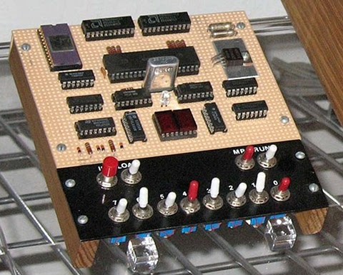
The COSMAC Elf, this version includes video graphics.


Is anyone using something along the lines of a microprocessor trainer in the classroom today outside a college level EE class?

Personally I can see two general approaches to this, with several possible variations on the two themes. Let's look at them, then I'll go into Blue Sky mode to talk about what I sort of wish for.

Some Ways to Bring Computer Hardware into Class
One is to fake it entirely with present-day hardware. After all, if it's possible to do a complete chip-level simulation of an 8-bit processor in Javascript, it shouldn't be much of a stretch to simulate an entire simple 8-bit microcomputer in a program with the ability to "see" all the operations inside simulated on the screen.

The problem is that this still really fails to make what's being taught "real". To the students, it becomes just another show to watch--one with no particular interest to most of them.

The other approach is to use an actual old microcomputer in class, like the Elf, with the students handling the system, measuring voltages or using logic probes to "see" the signals in the computer. Something more sophisticated would be using chip clips with LEDs on the various lines as a sort of multi-line logic probe. (Here is a place where an Elf or other RCA1802-based system would shine. The 1802 is a fully static processor. It can run at clocks speeds from 0Hz on up to its maximum clock speed, with clock changes on the fly. I have literally clocked 1802 systems by hand by connecting and disconnecting the clock line to +5V and Ground lines, counting out machine cycles as displays show the status of various system lines. There are not a lot of computer systems that can do that!)

An annotated image of a COSMAC Elf computer, showing the location of CPU, memory, and other ICs.


Between these two lie many other options. One would be to have a hardware board that connects to a modern computer through a common interface, like USB, where some I/O devices could be visible controlled by the computer (via lights, motors, etc.) and with lines exposed that can safely be probed by the students.

Another would be using a more modern hardware platform, perhaps based on one or more microcontrollers that emulate the function of an older system, exposing such things as memory access, control signals, and so on to the students. The board could include displays and LEDs to show the status of the lines, internal pseudo-registers, and so on. The operation of the entire system, both inside and outside the simulated ICs, could be made available to the student's eyes.

Part of what needs definition is the acceptable limitations of the system. In my own case, I see such a system as being an introduction to low-level hardware operation and control of that operation through software.

Blue Sky Dreaming
If I could have what I wanted without any effort on my part or a significant amount of the school's money, here's what I'd like:

Step 1
I would want to introduce a basic system that's very similar to the original Elf of 1976.

It would have:
  • Toggle switch inputs (to associate signals with data and to help teach binary),

  • A binary LED display and a two-digit hexadecimal display,

  • Very limited memory (about 128 to 256 bytes)(to teach how much can be done in limited memory, and to limit the size of early programs to sane sizes.

  • Exposed memory and I/O lines, possibly with LED monitors

  • Extra monitors, like maybe dual color LEDs to show data direction on I/O ports, etc.

  • A simple machine language with whole-word mnemonics.

  • The ability to operate at extremely low clock speeds (0-100Hz) as well as higher speeds (1-10MHz or something like.)


Step 2
  • Hexadecimal Keyboard

  • 512B to 1024B of RAM

After the first few lessons, the toggle switches would get old and I'd want to introduce a hexadecimal keypad. This would teach hexadecimal, and continue the association of computer instructions with numeric values in the computer. Presumably the connection between signal levels and numbers has been made using toggle switches.

With the easier input technique, it'd be nice to add some more memory, up to something like 512 bytes to 1 kilobyte.

Step 3
  • Keyboard with instruction mnemonics and hex digits

  • Perhaps more memory, up to about 4K

Next, a keyboard would be attached. Perhaps writing software to interface the keyboard to the system would be one of the Step 2 projects. While I'd be tempted to use an ASCII keyboard, I think a raw matrix keyboard would teach more. On this keyboard, machine language instructions and hexadecimal numbers would be mapped to each key. This would again speed programming, and reduce errors. The simple machine language I envision has a particular addressing mode associated with each mnemonic, so there's still no assembling of code required.

Step 4: A larger step
Next, I'd move to a more abstract level. I believe that the activities prior to this point would teach low level operations well enough to take this jump and still be able to show the connection between the two.

For step 4, the computer would get:

  • More memory. Anywhere from 4K to 64K. Perhaps it would start at 4K and grow as the students hit the limitations of each memory size.

  • A terminal connection to a current generation computer for keyboard and display, or an encoded keyboard and some other form of text display.

  • New firmware (probably activated from on-board with a mode switch), which would provide a fairly sophisticated command line interface with command editing, recall, etc., as well as an interactive programming language. The specific language doesn't matter too much, it could be a BASIC, a bash-alike, a LOGO, or an interactive form of some other compiled language.

  • Mass storage. Probably some modern semiconductor memory.


The point at this step would be writing high level programs to perform low level actions like those seen in the earlier steps. Seeing line levels and I/O operations performed, using bitwise operators, seeing the signals represented as numbers of various bases within the language (which I'd expect to support at least binary, hex, and decimal for representation and constants.)

Step 5
The final step with the low level computer would be to produce more sophisticated programs. These would be longer programs, probably projects done by groups of students over a few weeks in class. At this point the understanding of the program control structures and data structures should be a bridge to programming in the chosen language directly on the modern computer.

Final Thoughts
These thoughts are somewhat half-baked as they stand. I or someone would have to do some more work to really define this and turn it into hardware and software and a curriculum to go with it. Some points that need considering are the demarcation between this and a robotics class, common in many schools now (including the one at which I teach.) Also, how much class time does this merit? And so on.

Personally I think that using a micro trainer level system is simple enough to be mastered by most middle-school level students. I've got some actual experience with students to back that up, in addition to my own experience (I was 14 when I constructed my own Elf.) For the students, the information not only gives them an understanding of the underlying technologies of current systems, but would open the doors to embedded systems, far more common than conventional general purpose computers. Either way, it would make the computer far less a piece of technical magic controlled by somebody else and far more something comprehensible, and therefore controllable, by themselves.

Some related work--a 4 bit TTL Processor.

The fact is, all the steps above would probably be unnecessary and involve too many changes to the hardware platform to be practical in class. A more reasonable approach would probably be to go from a slightly more capable Step 1 computer directly to Step 4. This would reduce the opportunity for student disorientation as a result of seemingly constant hardware changes, and still be enough to get the key points across.

The activities I envision for Steps 2 and 3 could be either dropped or performed in either the initial or final configuration of the system. This would also simplify the system itself.

Friday, October 21, 2011

MeshCAM: An Inexpensive Commercial CAM Program

I was recently contacted by Robert Grzesek, developer of MeshCAM, a 3D CAM program. He'd seen my earlier article where I express some frustration with "free" software, particularly for CAM. The free software I tried usually did simple rasterized cuts of the object loaded, with the result that a lot of the design's detail was lost.

Robert offered me a free copy of MeshCAM if I'd blog about it. I took a look at the product information online and took him up on his offer.

MeshCAM is in the same price range as the other commercial CAM program I've been using--it's a hobbyist-affordable program. This is very nice, as so much of the available software is well beyond the budget of an amateur, or a small business where CAM work is a sideline without a large budget.

It's documentation and the tutorials are very good. Having recently gone through some tutorial-based training with some other programs that are from much larger companies in the past few days, I'm pretty well up to speed with what can go wrong with a tutorial. The MeshCAM tutorials are up to date and in sync with the current version of MeshCAM. They describe the process well from the basis of someone trying to get a specific task accomplished, they're not just a description of what appears in the menus.

At first, I wasn't sure that double-sided machining for full 3D objects was going to be covered, but it was, I just needed to stop anticipating possible problems quite so much.

Working with MeshCAM itself, I've opened up the provided files and a couple of files of my own. For the file types it accepts (STLs and DXFs, in addition to its own MCF format, plus a number of 2D image formats for image-based height maps), it opens the files without a problem and displays them properly. Wavefront OBJ files would be a nice addition, but then that's why I've got the open source program MeshLAB (which has no relation to the MeshCAM line of products) which is frustrating at times, but mostly does the job of object type conversion and it's free.

object display for MeshCAM
Above is an example of MeshCAM's display of an object. The way MeshCAM displays its axes is a bit cartoonish, but at least you won't have to worry about missing them. They can get in the way of small objects in the display screen. There may be a way to deal with that by changing the way they're displayed, but so far I've just moved or rotated my objects away to view detail then moved them back.

The thing that makes MeshCAM stand out for me at this point is its finishing abilities:
MeshCAM's many flexible finishing options.
It has built-in multi-pass finishing. I've managed to get the same results from Cut3D through a work-around. There, I create a finishing toolpath for one tool, save those toolpaths, then go back and define a different finishing pass, then save those toolpaths, and run them on the CNC one after the other.

MeshCAM doesn't require this. It gives a great set of finishing options for multiple tool passes right out of the box. I'm presently working on a model specifically to take advantage of these capabilities. Since much of what I'm doing is intended to have a high level of detail, I'm looking forward to seeing what comes off the CNC when I use MeshCAM to build the toolpaths.

MeshCAM displays the toolpaths it generates in the 3D view once they've been calculated, which gives a good first-look check to make sure that things came out right. There's no preview of the cutting operation built in to MeshCAM, however, as in Cut3D. Instead, a separate program, CutViewer is offered. Or you can do a "dry run" in most CNC control programs like EMC2 or Mach3 to see what the cutting will look like, at least as far as tool head movement is concerned.

The previews of the cutting operations have been one of my favorite features of Cut3D, so it's a feature I miss in a CAM program. I've gotten a higher degree of confidence from using this to see how the cutting operation will proceed ahead of time--the order of cuts is not always what you'd expect. The ability to check this during the CAM operation is very nice.

So I'd recommend planning to add CutViewer to your purchase if you buy MeshCAM, or make sure you're comfortable with your CNC control program's preview abilities. I'm using the preview abilities of EMC2's Axis view, myself.

Once I've finished the models I'll be trying out with MeshCAM, I'll be reporting on the final results. I'm planning both a flat relief object and a full 3D, 2-sided object.

Stay tuned...

Thursday, October 20, 2011

Objects of Rotation in Google Sketchup: A Problem of Nomenclature

I've been using Google's free Sketchup program for some 3D object designs lately. I've been using it for a while, but I only use it off and on, so my expertise is growing slowly.

Tonight I wanted to model something based on an Object of Rotation, which we all remember from math class is what you get when spin a shape around an axis. This is usually a trivial thing to do in both CAD and 3D design programs like AutoCAD, Lightwave, and so on. I couldn't remember how to do it offhand, so I did a quick search, expecting "sketchup object of rotation" would get me there in moments.

Technically Accurate, but Useless
I soon got lots of results for "Rotate Object", including a Sketchup tutorial video link. Unfortunately, I realized about 30 seconds into the video that it wasn't what I was looking for. It's a very nice tool for rotating an existing object's position around some arbitrary center of rotation, and possibly replicating it in a pattern around that center.

Nice, but not what I needed.

After a few frustrating attempts to rephrase the search to get what I wanted, I ended up just doing a search on what I knew is usually created as an object of rotation: a rocket.

"Sketchup rocket" yielded a couple of promising results. An amateur rocketry buff had instructions for drawing model rockets in Sketchup. The instructions for the nose cone were: how to draw an object of rotation in Sketchup.

Sketchup Follow Me Tool icon
Words Get In the Way
The tool for creating objects of rotation in Sketchup is the Follow-Me tool. In Sketchup terminology, an object of rotation is called a Lathed Object. Which makes perfect sense, if you already know it. (Thank you for the meme, Arthur Conan Doyle!)

So, to successfully search for how to create an object of rotation in Sketchup, use the terms "sketchup lathed object" or "sketchup follow me tool" to get what you want.

Hopefully this will show up when you search for "sketchup object of rotation" and save you some grief. ;)

Monday, October 3, 2011

CNC Rooster: Third Time's a Charm

In a prior post, I'd made a mistake handling the material when cutting a full 3D object using gcode files generated by Vectric's Cut3D CAM software. After that I tried again. That time things were going swimmingly until I got some gunk on a leadscrew that hung up the X axis and ruined the cut.

Well, I tried again today. After doing some preventative maintenance on my microCarve A4 CNC, testing it thoroughly and making sure of myself as well, I managed to turn out a small urethane rooster:

CNC 3D Rooster cut from Butter-Board using Cut3D and EMC2
Rooster, Side A


CNC 3D Rooster Back Side cut using MicroCarve A4 CNC Router
Rooster, Side B

The part turned out very well. The whole time the second side was cutting, I was fretting over how good my alignment would be. It turned out to be just fine.

The beak looks worse than it actually is because of a loose bit of plastic that'll come off when I scrape it with a thumbnail. It isn't perfect, however, because of the overcut depth I specified for the first side's cut. It's too deep for the thickness of the beak, and though the overall alignment of front and back side is excellent, the beak is at an angle, so one side is lower than the other. If I hadn't specified such a deep overcut, it would not have cut through this way.

Still, it'll clean up nicely.

Further Observations

The facets you see, particularly in areas like the chicken's breast, are part of the original 3D model. They aren't machining flaws. On the second side I cut the machining marks that are there are a little deeper than they should be because I trimmed my tab sizes down way too much, so they flexed a bit during machining.

Still, the overall quality of the part is such that I could clean it up to use as a casting master easily, if I were going to duplicate this part.


The Materials

The prior two tries were done using NC Proofboard, a urethane foam board, with densities of 60 and 48 lbs. per cubic foot. This last one was done in Butter-Board, which has a density of about 64 lbs per cubic foot. All are machinable plastics from Golden West Manufacturing.

60# NC Proofboard
The 60# proofboard was a very nice material. The cell size of the foam is very, very small and could easily be coated to smooth it enough to use a part made from it as a casting master. In fact, the mold release might be sufficient. It's very tough, and machines like a dream.

48# NC Proofboard
The 48# proofboard machines very easily as well, but tends to be a bit more brittle in thin sections than the 60# board. The cell size is about half again as large, but still small enough to be easy to coat, it'd just take more to do it--some sort of filler rather than a primer coat or a thick mold release agent.

Butter-Board
The Butter-Board machines to a fine, smooth surface. It takes a little more care in feed rates than the proofboards, which have a lot of resiliency thanks to being foamed products. But the completed part has an impeccable surface so far as the machining makes it so. It's not as tough in thin sections as the 60# proofboard, but it's stronger than the 48# board in thin sections in general, though it tends a bit toward the brittle.

I like all three materials quite a bit, and plan on getting some more of the Butter-board and 60# NC Proofboard soon for both business and hobby use.

Tooling
The rough cuts were done with a 1/8" 2 flute square end mill, the finishing cuts were done with a 1/16" 2 flute ball nose end mill. Both bits were purchased from IMService, at nice prices and the bits are very good. I was concerned that I may want to use single-flute bits, but these bits performed admirably with these materials. At some point I'll try a future cut with single-flute bits for comparison's sake, but these bits cut well, showed no propensity for clogging. They stayed sharp and cool through the cuts.

CAM Software
As to Cut3D, I'm quite happy with it so far, and I'm planning two more jobs for it in the immediate future. I'm also going to be giving MeshCAM a spin for a high relief piece of work in the near future, and I'll be reporting on that soon.

Tuesday, September 20, 2011

CNC with Vectric's Cut3D: It's Great, I'm So-So

After running through a bunch of free CAM software that didn't do what I wanted, I finally ended up where I pretty well knew I was going to end up. I downloaded a trial version of Vectric's Cut3D software.

I also happened to have some samples of machinable urethane plastics to try out, and the new software was just the thing to do that with.

I started with one of Vectric's sample files, the rooster statue. The statue is initially scaled to stand twelve inches tall. My material was about 3.5 by 2.4 by 0.9 inches in size. So I used Cut3D to scale the object, no problemo.

I positioned it in the block, added some tabs, again no problem.

Vectric Rooster Top Side Cut Into Urethane Block

Since this was my first time using Cut3D, my only concern as I went through the simple linear process of setting things up was what I would end up with in the way of files at the end. Would I get a file with some sort of pauses in it, during which I would do tool changes and material flips (to machine top and bottom), or would I have to edit these in, or what?

As it turned out, Cut3D produced four gcode files. Top rough cut, top finish cut, bottom rough cut, and bottom finish cut. For machines with tool changers, it can consolidate the files that have tool changes between them.

So this makes it easy. Load up the material, align the machine, run the rough cut for the side you start with, and wait for it to complete. Then change tools, recheck alignment, run the finish cut for that side. When that's over, flip the material, put in the correct bit for roughing, align, and run the other side's rough cut file. When that's complete, change bits and check alignment one last time then do the finish cut on the second side. Voila, you're done!

When machining a part on more than two sides, I presume that there are more files.

Well, Cut3D worked great. I didn't have the recommended post-processor file for my setup, but the Sherline inches was close enough so I tried that. I got the recommended post-processor for my setup from Vectric's support in my email today. The Sherline gcode worked fine, however.

The only thing that didn't work was me.

Here's my CNC setup. Here's what I got:

Vectric Rooster Top Side Cut Into Urethane Block
Front Side, so far so good...


Vectric Rooster Bottom Side Only Rough Cut Into Urethane Block, Upside-down from the front side.
Back side. Whoops! It's Upside-Down!


Everything started out fine, but I let myself get distracted by some visitors when I went to do the back side cut. I got the alignment right, but had it upside-down from the orientation I should have had it.

Moral of the story: put unambiguous markings on your workpiece to avoid mistakes during machining, and if a distraction gets introduced, set the work aside until it's gone. ;)

The material I'm machining out of is one of the denser varieties of NC Proofboard from Golden West Manufacturing. They're a short way away from me, and this was the first sample piece of their materials I've machined. And it machines like a dream! I may never machine wood again. Well, wood is awfully pretty so I'm sure I will, but not unless I really have to.

Their materials deserve their own article, so I'll be writing more about them once I've tried out a few more of my samples.

Upshot, Cut3D is a great program, and the price is great. I'm looking forward to doing a bunch of work with it, and possible upgrading to VCarve Pro some time later when I feel the need for more flexibility.

Monday, September 5, 2011

Motorola 68000 "Art"

I got an email message today about an image I posted some long time ago of a poster for the Motorola 68000 processor. The original image is a black and white test of image detail with my then-new cell phone.

Well, looking back at that old image is downright embarrassing. So here's a better one, and some other M68000-related images to go with it.


Motorola 68000 promotional poster with chip die image.
My poster from the Wescon conference after the 68000 was introduced. It came with a 68000 die tacky-glued to the poster, which I've since misplaced.


M68K Family Microprocessor User's Manual
The M68K Family User's Manual. Hardware Design Stuff.


MC68000 User's Manual
The older user's manual just for the 68000, this one's programming info.


HP 9800 User's Manual for M68000 CPU
Another 68000 User's Manual, from HP, pretty much the same as the above, but smaller and with an HP label on.


M68000 Cross Pascal Compiler Systems Guide
The Pascal Cross Compiler's Manual for the 68000


68000 Data Sheet Front Page, 1979
This is the front of a pre-release M68000 data sheet I got at a promo event in 1979. It got me pretty excited, I can tell you!


The programmer's manual for the whole 68K family.
Cover of the software book that goes with the 68K family hardware book, above.

Wednesday, August 3, 2011

The Entire Traveller RPG on One CD

Traveller is a science fiction RPG that appeared in 1977. Supplements and add-ons for this game appeared for another 6 years or so until a new version, MegaTraveller, appeared. Other versions have followed, with the most recent being Traveller from Mongoose Publishing.

The original game (PDF of contents) is now available from Far Future Enterprises, the company of Marc Miller, the original author of the game. It has several different editions of the core game rules, all the supplements, add-ons, and tie-in board games from the original publisher.

I originally bought the game in print form shortly after its appearance in 1977. I bought the first version of the Classic Traveller CD about 3 years ago. It was a tremendous resource, but it had some flaws. Now a new version of the CD has been released.

It's a huge improvement over the original CD. It contains additional versions of the rules that were not included on the first CD. Errors and poor scans have been corrected. For example, the book Scouts was poorly scanned on the old CT CD:

The New Traveller CD Has Cleaner Scans. New CD Above, Old Below. New scan is sharper and has higher resolution.


New Traveller CD Character Recognition:
CHARACTER GENERATION
A character is initially generated by rolling 2D for each of the six personal
characteristics: strength, dexterity, endurance, intelligence, education, and social
standing. This initial step is identical to that for standard character generation.
College: Any individual has the opportunity to attempt to obtain a college education.
In the Scout Service, a college education is generally necessary for an individual
to secure assignment to the Bureaucracy.
Any character may apply for admission to a college. The admission throw determines
if the character is admitted and actually starts attending college; if the throw
is not achieved, the character remains age 18 and may then directly attempt to
enlist in the Scouts. Once admitted to college, the individual determines his or her
success in college for the full four years; if the success throw is not achieved, the
individual has aged one year (to age 19)


Old Traveller CD Character Recognition:
CHARACTER GENERATION
A character is initially generated by rolling 20 for each of the six personal
characteri~t8cs: strength, dexterity, endurance, intelligence, education, and social
standrng Tnos notla step s dsntical to that for sranasrd character genera! on.
C0I.g.: Any lnaivlobal has Ine op~ortunry la attempt to obra n s col sgs ed-eation
n tna Scnn Servlcs. a col eoe sa~cation:o "oeners l.v neceo osrv for an me v d ~ a l
to secure assignment to the Bureaucracy.
Any character may apply for admission to a college. The admission throw determine8
if the character is admitted and actually starts anendlng college; 8f the throw
is not achieved, the character remains age 18 and may then directly attempt to
enlist ~n the Scouts. Once admitted to college, tha individual determines hieor her
SUCCBSD ~n cdlege for the full four years; if the success throw is not achieved, the
indlvldual has aged one year Ito age 191


Missing pages and other problems have been fixed.

If you're looking for the best value in RPGs, check this out.

Wednesday, July 20, 2011

More Traveller RPG Than You Can Fit in a Low Berth

In the 1970s I regularly shopped at a local militaria/war game shop in Walnut Creek, CA called The Centurion. In 1977 they had a new game, called Traveller. When I bought it, the guy at the shop commented "I thought of you when I ordered this one. You're the first one to get it, let me know what you think of it." I was a sucker for anything in the way of science fiction games, so he had me tagged. If there was a blurry mimeograph in a ziplock bag with a spaceship on it, I'd buy it.

I still have the game today:

1977 Traveller RPG Game Box
My original Traveller game from 1977


1977 Traveller Game Set
What's inside the box.


Needless to say, I like the game. A lot. For lots of reasons.

Fast Forward to 2007
Then, about three and a half years ago, I found out that Traveller had become available on CD. Not just the original game that I owned, but all the expansions that had been offered by its publisher, Game Designer's Workshop.

Traveller CD and Journal of the Travellers' Aid Society CD
The Classic Traveller CD and the JTAS Magazine CD


All the expansions means:

All the additional rule books.
All the scenario, campaign, and adventure books.
The several board games related to the game.
The later editions of the rules.
Etc., etc.

In other words, a HEAP of stuff to read and enjoy.

As you can see from the picture above, I also bought another CD with it. That one contains the magazine "Journal of the Traveller's Aid Society", the magazine for the game. What a treasure trove of gaming stuff!

Fast Forward to TODAY
The Classic Traveller CD got an update earlier this year. It's got more versions of the rules, corrected and improved scans of some of the material from the new CD, and so on. For those that purchased the original CD, the new one costs only $7.

Unless you order an additional CD when you order the update. In that case, the $7 cost of the update CD is refunded. Since there are many different CDs for many different editions of Traveller available from Far Future Enterprises, it wasn't going to be hard for me to take advantage of that offer!

But Wait, There's More!

Not only that, but there's a special sale going on called 443. Buy three CDs and the fourth is free (thus Four for Three: 443), four for the price of three. Since two more CDs of "Classic" Traveller material were out, I was halfway there already. Add to that the CD of the latest version of Traveller, still under development (Traveller 5), and the forthcoming Traveller 4 CD (I have the core book for this version, but not some of the other books I've seen widely touted by other players on the web, which will be on this CD), and I'm good.

Today the mail held this:

A collection of Traveller RPG game CDs
My Amazing New Traveller CDs. One more will arrive after it becomes available at the end of August.


The T4 CD was a pre-order, so it's not in the picture. It'll be here soon enough. I've got plenty to keep me occupied until it arrives!

Here's the new Classic Traveller CD:
The new Classic Traveller CD.
Bling! The new CT CD. Not just an amazing game collection, it also makes a great diffraction grating! Read the books as you use it to analyze spectra of far off stars!


The back of the CD, with the stamp of Duke Norris
Duke Norris has my back. There's nothing like having the nobility of the Third Imperium of Man keeping an eye out for your data. Beats counting on some drunken X-Boat driver to get it to you.

Tuesday, July 12, 2011

CNC Projects: 10 Basic Rules I've Learned


Here are some basic rules I use when selecting or setting up CNC projects. Let me know your rules, or any tweaks you see to mine. Thanks!

1. Don't make anything that you can buy easily, unless you have some specific reason that over-rides the extra cost, effort, and likely unforeseen problems.

2. Remove as little material as possible. Look carefully at item placement in your material stock, different ways of cutting the piece, possible design changes, etc. to reduce the amount of cutting and the amount of material to be removed.

3. Plan your cuts so that the ones that most depend on the accuracy of the bit's size are done with a fresh bit. Bits wear while cutting, if you're planning on cutting, say, a 1/4" dado with a 1/4" bit, you should do it while the bit still has a 1/4" diameter to minimize post-machining to make things accurate.

4. Test your ideas in scrap material first, unless it's a minor variation on something you've already done. Chances are you'll either find a problem you didn't anticipate, or figure out a way to do it better on the next go.

5. Be fanatical about your means of mounting the work. The accuracy and success of the machining relies on it, so think about this as much as you think about the rest of the project.

6. Once you find something that works, build on it. Once you've developed a routine for mounting, cutting, registering, or whatever that regularly produces the results you want, keep doing it. It helps to take notes and pictures for reminders in case there's a break in operations that leaves you a bit rusty on how you did it before.

7. If something isn't working quite, don't keep tolerating it. Fix it, replace it, find another way. It'll be worth the time saved later.

8. Learn from others. Watch videos online, visit other folks' websites, visit with other CNC machinists, see how it's done with different machines or in different areas than your individual interests.

9. Do "science" projects. Plan and develop projects just for the sake of trying out something new or exercising a different procedure. Just like doing a first work in scrap, they'll save you time in the end.

10. Make one complete finished item before you cut out a whole set of parts production-line style. While it costs a fair bit of time in setup to go through once for the prototype, then go back and start over for production, it's better than finding out you've got a stack of parts that won't work when you get to final assembly.

My CNC Website

Monday, June 20, 2011

microCarve CNC Project: Collectable Spoon Rack

Here's the initial results of my spoon rack projects as mentioned in prior posts:

My Spoon Rack Project Idea

Decorative Motifs for the Spoon Rack

Here's the first one:

A new spoon rack I designed and built, made with my microCarve A4 CNC

CNC cut collectable spoon rack.

Face on view of designs cut with my CNC machine.


I have parts for 3 cut out. There's a bit of manual finish work yet to do for the remaining ones. The weather has turned hot and dry, which is good for the staining work.

Tuesday, June 7, 2011

Decorative Motifs in GCode for CNC

My manual gcode workflow is getting better. Until I'm in a position to pick up some commercial CAM software (probably early fall later this year), I'm getting by with manual processes. It's not too bad, the fact is there's still a lot I'm learning about machining while I work. The lack of software doesn't mean lack of projects at this point.

I have a much better idea of how things are going to turn out when I design them now, so I'm not wasting nearly as much time designing things that aren't going to work out when I make them now. Here are my latest test cuts:

Decorative motifs for woodworking cut with microCarve A4 CNC
Testing the motifs with different depths of cut.


These are some decorative motifs for my spoon rack project. My first drawings were of designs that were far too involved for this project's scale. This set, above, turned out pretty much exactly as I drew them on the green engineering paper. In these tests I was trying out different depths of cut (set using variables in the gcode.)

The first fully complete and ready for public viewing spoon rack should be done soon. I've been going back and forth between different elements of the project, touching things up and trying to get the different parts all in sync, not only in mechanical properties but also in the coding standards I use for the files. I'm intending to publish this as a project on my website once it's done.

My present workflow goes something like this:

  1. Come up with idea.

  2. Draw it out on green engineering pad.

  3. Lay out dimensions on drawing relative to a selected origin for the piece.

  4. Open up EMC2 and a text editor.

  5. Write out gcode in the text editor, checking the work in EMC2's preview often.

  6. Transfer the file that looks good on my editing system to the CNC controller.

  7. Check dimensions and movement manually before loading a workpiece on the machine.

  8. Do an "air cut" of the file.

  9. Put some scrapwood on the CNC. Check level and positioning.

  10. Check origins and movement limits again.

  11. Do a test cut.

  12. Go back and make any design changes and repeat the test cut, if req'd.

  13. Cut the real thing. Repeat as necessary.


At this point I'd say that the guesswork that happens throughout this process is far, far less than it was even a week ago. That means I can do stuff faster. I also added a wireless router to my CNC controller computer's setup so that I can get files there from my design system in the house faster and easier, as well as do edits to the original files there rather than ending up with version control madness.

I'm also getting much better at mounting up work in the machine accurately, and in checking movement and dimensions on the machine before I start a cut. This also means the work goes faster. Which means I can make more test cuts, and still have time to make more finished pieces.

Thursday, May 26, 2011

Mount an HF Router on Your CNC, Quick and Easy

I posted my design for mounting the inexpensive Harbor Freight 1/4" trim router #44914 to a CNC on my website today. I've posted a dimensional drawing of the base plate, and given instructions for the rest (it's bone-simple, really!) Click the pic below to go right to it:

A quick and dirty spindle mount for the HF 44914 router

Tuesday, May 24, 2011

My GCode Gets a Bit Tricker: Working with the microCarve A4 CNC

We collect souvenir spoons when we travel. Unfortunately, we overflowed the little wooden rack that holds our spoons several years ago:

A pretty wooden rack for holding little silver spoons from around the world.

We have almost twice as many little spoons as will fit on the rack. So I decided that a good CNC project would be making some additional racks that will hold the additional spoons, plus any extras we acquire in the near future.


Building the Toolchain

I've been using this project as a sort of pilot for putting together an automated toolchain for my CNC. You know, draw the object in CAD, convert it to gcode, and cut on the CNC. In the past I've just used image maps as depth maps and hand-written gcode to produce things. This project seemed to have about the right level of complexity for an initial project with a new set of tools.

At first, I had already designed the rack for the spoons themselves by hand on paper, and written gcode to match. But I laid this aside and tried out several CAD tools. The CAD tool that I ended up with a decent file from in the least time was Google Sketchup, running on my Mac. Unfortunately, Sketchup doesn't write in the CAM-friendly file formats. So I pulled MeshLab, which converted a Sketchup Collabra file to STL for CAM.

close-up of the spoon rack
Close-Up of the Item that Inspired my Project


The next step was CAM. After spending over a week trying out different free CAD packages (see below for why I'm starting with no-cost software), I was getting antsy to start cutting something. After three goes with different CAM packages on three OSes, and still no results worth cutting, I just decided to pull out the gcode and give it a once-over.

GCode FTW

I did a quick third pass over my gcode program on paper, then typed it in on my EMC2 system with gedit. The EMC2 preview was, as always, very helpful. It let me catch a bogus Z-value. Once that was fixed, I plunked down a piece of MDF for the trial run and let 'er rip.

The first go at cutting my own little spoon rack.
My first go at the spoon rack's shelf, the back is another piece. But I've got an idea for improving on this...

The piece cut out very nicely. I ran it in three passes, the support for the piece was pretty minimal, so you can see where each pass cut across. A bit of sandpaper would fix this well enough.

However, I think I'd rather do the little shelf out of 1/4" stock. I used 1/2" because my prototype uses that thickness. But it's not like there's a lot of stress on the part from the spoons. So I'm going to re-build my code for a 1/4" thick piece before making the "production" units (probably three of them.) Then I may try to use the automated toolchain again for the backs of the spoon racks (all I have in gcode at this point is the little shelf.)

Why Free?
I don't have any aversion to spending money for quality software. In fact, much the opposite. However, I've already spent the money I had budgeted for the CNC. Plus I've tread on my money set aside for travel this summer because of some unexpected household expenses.

For the time being, I'm being a bit hairshirt when it comes to software.

I'm very happy with EMC2 for my CNC software at this point.

Sketchup is pretty well doing OK for me for CAD right now, though there are things I will want to do later that I'm not sure it does easily or well. When money permits, what I'd really like to do is pick up ZBrush. Hopefully within a year or so. Sooner if possible.

For CAM, I'm thinking that I'll want to pick up something like Cut3D from Vectric. It seems to have the functions I want. Cut2D is a possibility, too. I'll be doing the free trial on each in the not-too-distant future.

In the meanwhile, if you know of some free CAM software that doesn't just treat an STL object as something to be rastered over, drop me a note. I'm completely OS-agnostic. Most recently I was doing CAD in MacOS, running CAM (FreeMill, a good package but didn't do what I needed) on Windows, and I'm driving the CNC with EMC2 on Linux.

Friday, May 20, 2011

microCarve A4 CNC Assembly Instructions Online

MicroCarve A4 CNC router, base assembly

I've posted step by step instructions of how I assembled my microCarve A4 CNC router on my website:

microCarve A4 Assembly

This is the first component of a new section of my site dedicated to CNC machining. Since I've gotten the A4, I've really enjoyed spending a lot of time working with it, learning what I can do with it. I'm still a long way away from solidly competent, but it's a state I'm enjoying working toward. And the stuff I'm making along the way is fun, too.

So, as time allows, I'll be expanding the content I have from the CNC Machining home page on my site to include project info, tips and tricks I learn along the way, and links to information from others that I've found especially helpful (if I linked everything that was helpful to me, it'd overwhelm me entirely!)

Monday, May 16, 2011

Fundraising with my microCarve A4 CNC

This last weekend, my daughters went to a special SacAnime Con. It was a Japan Disaster Relief con, which raised $6556. My daughters had some space on a vendor table at the con, and last week they asked me of I could make something that they could sell to raise money for disaster relief.

I set aside my other projects, and turned out a number of little "remembrance tablets", as you see in the pictures here. The idea was that for each one we sell, we'd pass on the profits to Second Harvest Japan, Japan's first food bank. We think they do great work, whether there's been a disaster or not. So it seemed like a good cause to support.

The tablets are about 1.5 by 2.25 inches (~3.7 x 6 cm), hung on a cord so to be worn around the neck. Each design is bilingual, English and Japanese. I took a bit of a liberty with the "Prosper" tablets, the Japanese is more properly "Prosperity" but the English word was too long to fit on the tablet with the level of detail I'm able to carve at present.

Tohoku disaster remembrance: Recovery in Kanji and English.

Tohoku disaster remembrance token: Health in Kanji and English.

Tohoku disaster remembrance tablet: Prosper in Kanji and English.

Tohoku Rememberance Tablet: Tsunami of Love in Kanji/Hirigana and English.
This tablet is larger than the others, measuring 2 x 3.5 inches (5 by 9 cm). The detail is far more striking in person than in this photo where the light from overhead washes it out.

There were some other designs that I'll try to get decent photos of soon.

Unfortunately, we weren't able to sell all of these tablets, I still have many left. If you're interested, drop me an email. I have instances of all the above plus a couple of other designs available. And it'll still benefit Japan--that's what these were made for.

Making the Tohoku Remembrances

These were made using the image-to-gcode converter included with EMC2. It's got some serious quirks to its behavior I had to overcome. When I originally set out to make these, I had two ways I could do it. I considered writing my own gcode programs by hand, and using the image converter.

I decided to go with the image converter because I thought it would allow me to make more different designs faster than writing my own programs by hand. Unfortunately, I was wrong. The time I spent learning the quirks of the image converter, with what sort of feature depth I would get, how much of a border around the image, and so on was far, far more than I expected. It would have been far more productive to hand-code the simple designs I ended up with.

My original ideas were more involved, more like the "Tsunami of Love" design, above, which was carved last of all at about midnight before the con. On each iteration I ended up simplifying my designs while trying to get the sort of features I wanted in the carving. I wanted to have the Kanji characters carved into the wood, originally, but I couldn't control the way the software managed the depth and width of the lines when doing this. The Kanji would end up barely visible, and the English characters were unreadable.

A CNC Success, in a Way
I took advantage of this project as an initial test of my ability to do some small-scale production with my new CNC. As a fundraiser, I have to say it didn't work out so well, but as a first go at some small-scale, simple production it was a success--barely.

My decision to rely on someone else's software that I don't entirely understand was a real weak point, but I still managed to turn out a decent number of pieces of work before the con. The investment of time into each one was over double what I originally expected. Still, I got them done within the time margin I provided for this project. Barely.

I'm happy with the results, particularly the Tsunami of Love item, and think I could go on to make some better stuff. Though I clearly need to work on my toolchain. In the future I need to have a tool at hand that I'm familiar with that will produce better results than the free image-to-gcode converter. And I need to have something that's more powerful than hand-written gcode programs for all but the simplest designs.

I've learned a lot over the past week, both about myself and my CNC machine. Now I'm ready for the next step.

Friday, May 6, 2011

What I Learned with My CNC Machine Today

I'm in the second day of a one day project today. Hopefully I'll finish it on Day 3.

But, at each step I'm learning new and useful things.

Yesterday I learned:


  1. There's a point where you need to stop writing gcode by hand, and use CAD/CAM.

  2. Doing tool compensation by hand is a real bear.

  3. Don't think of designs that are too much more elaborate than what you've actually made before.


Today's Lessons:


  1. When your test piece is MDF and your work piece is real wood, there are going to be differences.

  2. Grain and cutting direction matter more when using a CNC than when you route by hand, where you make all sorts of little compensations that you don't even notice.

  3. Just because this piece looks like the last piece you cut doesn't mean that it really is, even if it's a piece off the same stock. This can be really important when you're clamping your work down.


Nonetheless, I managed to avoid anything worse than some minor marring of the surface of one work piece. It's still usable for the project.

So far, I've succeeded at using the CNC as a really complicated and finicky power planer. Unlike the first time I used a power planer, it did not throw a piece of wood across the shop at barely subsonic velocities. One piece came a bit loose in the clamp is all. I shut down the machine in time, re-clamped it, and picked up where I left off.

Wednesday, May 4, 2011

First Attempt at Engraving an IC with my CNC

I decided to try doing a smaller, more precise job with my microCarve A4 CNC today. I took some of my GCode program from yesterday, scaled it down (fortunately I provided variables to do all that automatically for me) and added a chip number in characters that I hoped would show with the bit I'm using.

Here's what I got:

CNC Engraved IC. The bit isn't quite sharp enough for the level of detail.
My first shot at engraving an IC top. It's not really an 8085 microprocessor, it's a dead ROM I happened to have hanging around.


The cut widths are about 35 thousandths. Too large for the level of detail in the smaller key pattern. The single large key above is scaled three times larger than the smaller keys. The base leg length for the small keys (the smallest segment size) is 25 thousandths. So it's easy to see why it didn't quite come out.

Still, the accuracy would have been plenty good, if I'd had a sharp enough bit.

Onward and upward! :)