Yesterday, I learned that ZBrush (my 3D design program) now has an extension that lets it directly export files I can use with my Computer Aided Manufacturing (CAM) programs. I spent most of my work time today testing the output of various designs to see how they looked.
ZBrush has this 'built-in' since version 4R6 came out, it was available as a plug-in before, but since it calls itself a 3D printing plug-in, I ignored it, assuming it was software to sent object data to one or more of the commercial 3D printing services, like Shapeways. Turns out it's an exporter for standard 3D object file formats like .stl.
This is a huge improvement for my workflow of going from design to a finished part prototype in the real world. Before I had to use a very complex conversion program. Its control panel makes the flight deck of a 747 look simple. And if I didn't get the settings just right, I could get some really nasty effects in the final machining. Using the same settlings over again doesn't work, I had to adjust things based on the size of the object, the scale of features on it, the size of the material it would be cut out of, the relative size of the tool, etc., etc.
Now that difficult & frightening step is gone. I do a couple of passes to simplify the 3D object design as much as possible without losing detail (which I was doing anyway, it speeds up everything later), set a couple of simple settings in the exporter, like the real-world size the final object will be, then export.
The resulting files load just fine into the two different programs I use that create the list of instructions for my CNC machine to cut the 3D object out of a solid block of some material (usually a polyurethane plastic). I did a dry run to set up two test files tonight--doing everything short of actually making the parts. Tomorrow I plan to make an actual part from a new file as a final test. Probably something fun.
For those interested in trying this at home, I use both MeshCAM and Vectric's Cut3D for CAM. Cut3D is my usual preference, though I'm using an older version of MeshCAM (4). I prefer Cut3D's interface for setting tabs, and its included machining preview.
Both produce excellent GCode for my CNC (a MicroCarve A4 driven by EMC2 and a Gecko G540 controller.)
For doing image depth maps, I use EMC2's built in facility, though if you want to bypass the copious experimentation & two pages of notes I use to get it looking good, you might want to look into one of the dedicated commercial programs for this.
Showing posts with label gcode. Show all posts
Showing posts with label gcode. Show all posts
Tuesday, November 19, 2013

Friday, October 21, 2011
MeshCAM: An Inexpensive Commercial CAM Program
I was recently contacted by Robert Grzesek, developer of MeshCAM, a 3D CAM program. He'd seen my earlier article where I express some frustration with "free" software, particularly for CAM. The free software I tried usually did simple rasterized cuts of the object loaded, with the result that a lot of the design's detail was lost.
Robert offered me a free copy of MeshCAM if I'd blog about it. I took a look at the product information online and took him up on his offer.
MeshCAM is in the same price range as the other commercial CAM program I've been using--it's a hobbyist-affordable program. This is very nice, as so much of the available software is well beyond the budget of an amateur, or a small business where CAM work is a sideline without a large budget.
It's documentation and the tutorials are very good. Having recently gone through some tutorial-based training with some other programs that are from much larger companies in the past few days, I'm pretty well up to speed with what can go wrong with a tutorial. The MeshCAM tutorials are up to date and in sync with the current version of MeshCAM. They describe the process well from the basis of someone trying to get a specific task accomplished, they're not just a description of what appears in the menus.
At first, I wasn't sure that double-sided machining for full 3D objects was going to be covered, but it was, I just needed to stop anticipating possible problems quite so much.
Working with MeshCAM itself, I've opened up the provided files and a couple of files of my own. For the file types it accepts (STLs and DXFs, in addition to its own MCF format, plus a number of 2D image formats for image-based height maps), it opens the files without a problem and displays them properly. Wavefront OBJ files would be a nice addition, but then that's why I've got the open source program MeshLAB (which has no relation to the MeshCAM line of products) which is frustrating at times, but mostly does the job of object type conversion and it's free.

Above is an example of MeshCAM's display of an object. The way MeshCAM displays its axes is a bit cartoonish, but at least you won't have to worry about missing them. They can get in the way of small objects in the display screen. There may be a way to deal with that by changing the way they're displayed, but so far I've just moved or rotated my objects away to view detail then moved them back.
The thing that makes MeshCAM stand out for me at this point is its finishing abilities:
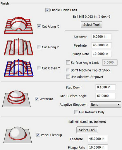
It has built-in multi-pass finishing. I've managed to get the same results from Cut3D through a work-around. There, I create a finishing toolpath for one tool, save those toolpaths, then go back and define a different finishing pass, then save those toolpaths, and run them on the CNC one after the other.
MeshCAM doesn't require this. It gives a great set of finishing options for multiple tool passes right out of the box. I'm presently working on a model specifically to take advantage of these capabilities. Since much of what I'm doing is intended to have a high level of detail, I'm looking forward to seeing what comes off the CNC when I use MeshCAM to build the toolpaths.
MeshCAM displays the toolpaths it generates in the 3D view once they've been calculated, which gives a good first-look check to make sure that things came out right. There's no preview of the cutting operation built in to MeshCAM, however, as in Cut3D. Instead, a separate program, CutViewer is offered. Or you can do a "dry run" in most CNC control programs like EMC2 or Mach3 to see what the cutting will look like, at least as far as tool head movement is concerned.
The previews of the cutting operations have been one of my favorite features of Cut3D, so it's a feature I miss in a CAM program. I've gotten a higher degree of confidence from using this to see how the cutting operation will proceed ahead of time--the order of cuts is not always what you'd expect. The ability to check this during the CAM operation is very nice.
So I'd recommend planning to add CutViewer to your purchase if you buy MeshCAM, or make sure you're comfortable with your CNC control program's preview abilities. I'm using the preview abilities of EMC2's Axis view, myself.
Once I've finished the models I'll be trying out with MeshCAM, I'll be reporting on the final results. I'm planning both a flat relief object and a full 3D, 2-sided object.
Stay tuned...
Tweet
Robert offered me a free copy of MeshCAM if I'd blog about it. I took a look at the product information online and took him up on his offer.
MeshCAM is in the same price range as the other commercial CAM program I've been using--it's a hobbyist-affordable program. This is very nice, as so much of the available software is well beyond the budget of an amateur, or a small business where CAM work is a sideline without a large budget.
It's documentation and the tutorials are very good. Having recently gone through some tutorial-based training with some other programs that are from much larger companies in the past few days, I'm pretty well up to speed with what can go wrong with a tutorial. The MeshCAM tutorials are up to date and in sync with the current version of MeshCAM. They describe the process well from the basis of someone trying to get a specific task accomplished, they're not just a description of what appears in the menus.
At first, I wasn't sure that double-sided machining for full 3D objects was going to be covered, but it was, I just needed to stop anticipating possible problems quite so much.
Working with MeshCAM itself, I've opened up the provided files and a couple of files of my own. For the file types it accepts (STLs and DXFs, in addition to its own MCF format, plus a number of 2D image formats for image-based height maps), it opens the files without a problem and displays them properly. Wavefront OBJ files would be a nice addition, but then that's why I've got the open source program MeshLAB (which has no relation to the MeshCAM line of products) which is frustrating at times, but mostly does the job of object type conversion and it's free.
Above is an example of MeshCAM's display of an object. The way MeshCAM displays its axes is a bit cartoonish, but at least you won't have to worry about missing them. They can get in the way of small objects in the display screen. There may be a way to deal with that by changing the way they're displayed, but so far I've just moved or rotated my objects away to view detail then moved them back.
The thing that makes MeshCAM stand out for me at this point is its finishing abilities:
It has built-in multi-pass finishing. I've managed to get the same results from Cut3D through a work-around. There, I create a finishing toolpath for one tool, save those toolpaths, then go back and define a different finishing pass, then save those toolpaths, and run them on the CNC one after the other.
MeshCAM doesn't require this. It gives a great set of finishing options for multiple tool passes right out of the box. I'm presently working on a model specifically to take advantage of these capabilities. Since much of what I'm doing is intended to have a high level of detail, I'm looking forward to seeing what comes off the CNC when I use MeshCAM to build the toolpaths.
MeshCAM displays the toolpaths it generates in the 3D view once they've been calculated, which gives a good first-look check to make sure that things came out right. There's no preview of the cutting operation built in to MeshCAM, however, as in Cut3D. Instead, a separate program, CutViewer is offered. Or you can do a "dry run" in most CNC control programs like EMC2 or Mach3 to see what the cutting will look like, at least as far as tool head movement is concerned.
The previews of the cutting operations have been one of my favorite features of Cut3D, so it's a feature I miss in a CAM program. I've gotten a higher degree of confidence from using this to see how the cutting operation will proceed ahead of time--the order of cuts is not always what you'd expect. The ability to check this during the CAM operation is very nice.
So I'd recommend planning to add CutViewer to your purchase if you buy MeshCAM, or make sure you're comfortable with your CNC control program's preview abilities. I'm using the preview abilities of EMC2's Axis view, myself.
Once I've finished the models I'll be trying out with MeshCAM, I'll be reporting on the final results. I'm planning both a flat relief object and a full 3D, 2-sided object.
Stay tuned...
Tuesday, September 20, 2011
CNC with Vectric's Cut3D: It's Great, I'm So-So
After running through a bunch of free CAM software that didn't do what I wanted, I finally ended up where I pretty well knew I was going to end up. I downloaded a trial version of Vectric's Cut3D software.
I also happened to have some samples of machinable urethane plastics to try out, and the new software was just the thing to do that with.
I started with one of Vectric's sample files, the rooster statue. The statue is initially scaled to stand twelve inches tall. My material was about 3.5 by 2.4 by 0.9 inches in size. So I used Cut3D to scale the object, no problemo.
I positioned it in the block, added some tabs, again no problem.

Since this was my first time using Cut3D, my only concern as I went through the simple linear process of setting things up was what I would end up with in the way of files at the end. Would I get a file with some sort of pauses in it, during which I would do tool changes and material flips (to machine top and bottom), or would I have to edit these in, or what?
As it turned out, Cut3D produced four gcode files. Top rough cut, top finish cut, bottom rough cut, and bottom finish cut. For machines with tool changers, it can consolidate the files that have tool changes between them.
So this makes it easy. Load up the material, align the machine, run the rough cut for the side you start with, and wait for it to complete. Then change tools, recheck alignment, run the finish cut for that side. When that's over, flip the material, put in the correct bit for roughing, align, and run the other side's rough cut file. When that's complete, change bits and check alignment one last time then do the finish cut on the second side. Voila, you're done!
When machining a part on more than two sides, I presume that there are more files.
Well, Cut3D worked great. I didn't have the recommended post-processor file for my setup, but the Sherline inches was close enough so I tried that. I got the recommended post-processor for my setup from Vectric's support in my email today. The Sherline gcode worked fine, however.
The only thing that didn't work was me.
Here's my CNC setup. Here's what I got:
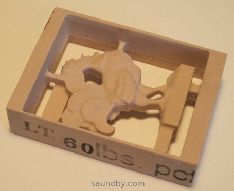

Everything started out fine, but I let myself get distracted by some visitors when I went to do the back side cut. I got the alignment right, but had it upside-down from the orientation I should have had it.
Moral of the story: put unambiguous markings on your workpiece to avoid mistakes during machining, and if a distraction gets introduced, set the work aside until it's gone. ;)
The material I'm machining out of is one of the denser varieties of NC Proofboard from Golden West Manufacturing. They're a short way away from me, and this was the first sample piece of their materials I've machined. And it machines like a dream! I may never machine wood again. Well, wood is awfully pretty so I'm sure I will, but not unless I really have to.
Their materials deserve their own article, so I'll be writing more about them once I've tried out a few more of my samples.
Upshot, Cut3D is a great program, and the price is great. I'm looking forward to doing a bunch of work with it, and possible upgrading to VCarve Pro some time later when I feel the need for more flexibility.
Tweet
I also happened to have some samples of machinable urethane plastics to try out, and the new software was just the thing to do that with.
I started with one of Vectric's sample files, the rooster statue. The statue is initially scaled to stand twelve inches tall. My material was about 3.5 by 2.4 by 0.9 inches in size. So I used Cut3D to scale the object, no problemo.
I positioned it in the block, added some tabs, again no problem.
Since this was my first time using Cut3D, my only concern as I went through the simple linear process of setting things up was what I would end up with in the way of files at the end. Would I get a file with some sort of pauses in it, during which I would do tool changes and material flips (to machine top and bottom), or would I have to edit these in, or what?
As it turned out, Cut3D produced four gcode files. Top rough cut, top finish cut, bottom rough cut, and bottom finish cut. For machines with tool changers, it can consolidate the files that have tool changes between them.
So this makes it easy. Load up the material, align the machine, run the rough cut for the side you start with, and wait for it to complete. Then change tools, recheck alignment, run the finish cut for that side. When that's over, flip the material, put in the correct bit for roughing, align, and run the other side's rough cut file. When that's complete, change bits and check alignment one last time then do the finish cut on the second side. Voila, you're done!
When machining a part on more than two sides, I presume that there are more files.
Well, Cut3D worked great. I didn't have the recommended post-processor file for my setup, but the Sherline inches was close enough so I tried that. I got the recommended post-processor for my setup from Vectric's support in my email today. The Sherline gcode worked fine, however.
The only thing that didn't work was me.
Here's my CNC setup. Here's what I got:
Front Side, so far so good...
Back side. Whoops! It's Upside-Down!
Everything started out fine, but I let myself get distracted by some visitors when I went to do the back side cut. I got the alignment right, but had it upside-down from the orientation I should have had it.
Moral of the story: put unambiguous markings on your workpiece to avoid mistakes during machining, and if a distraction gets introduced, set the work aside until it's gone. ;)
The material I'm machining out of is one of the denser varieties of NC Proofboard from Golden West Manufacturing. They're a short way away from me, and this was the first sample piece of their materials I've machined. And it machines like a dream! I may never machine wood again. Well, wood is awfully pretty so I'm sure I will, but not unless I really have to.
Their materials deserve their own article, so I'll be writing more about them once I've tried out a few more of my samples.
Upshot, Cut3D is a great program, and the price is great. I'm looking forward to doing a bunch of work with it, and possible upgrading to VCarve Pro some time later when I feel the need for more flexibility.
Tuesday, May 24, 2011
My GCode Gets a Bit Tricker: Working with the microCarve A4 CNC
We collect souvenir spoons when we travel. Unfortunately, we overflowed the little wooden rack that holds our spoons several years ago:

We have almost twice as many little spoons as will fit on the rack. So I decided that a good CNC project would be making some additional racks that will hold the additional spoons, plus any extras we acquire in the near future.
Building the Toolchain
I've been using this project as a sort of pilot for putting together an automated toolchain for my CNC. You know, draw the object in CAD, convert it to gcode, and cut on the CNC. In the past I've just used image maps as depth maps and hand-written gcode to produce things. This project seemed to have about the right level of complexity for an initial project with a new set of tools.
At first, I had already designed the rack for the spoons themselves by hand on paper, and written gcode to match. But I laid this aside and tried out several CAD tools. The CAD tool that I ended up with a decent file from in the least time was Google Sketchup, running on my Mac. Unfortunately, Sketchup doesn't write in the CAM-friendly file formats. So I pulled MeshLab, which converted a Sketchup Collabra file to STL for CAM.

The next step was CAM. After spending over a week trying out different free CAD packages (see below for why I'm starting with no-cost software), I was getting antsy to start cutting something. After three goes with different CAM packages on three OSes, and still no results worth cutting, I just decided to pull out the gcode and give it a once-over.
GCode FTW
I did a quick third pass over my gcode program on paper, then typed it in on my EMC2 system with gedit. The EMC2 preview was, as always, very helpful. It let me catch a bogus Z-value. Once that was fixed, I plunked down a piece of MDF for the trial run and let 'er rip.

The piece cut out very nicely. I ran it in three passes, the support for the piece was pretty minimal, so you can see where each pass cut across. A bit of sandpaper would fix this well enough.
However, I think I'd rather do the little shelf out of 1/4" stock. I used 1/2" because my prototype uses that thickness. But it's not like there's a lot of stress on the part from the spoons. So I'm going to re-build my code for a 1/4" thick piece before making the "production" units (probably three of them.) Then I may try to use the automated toolchain again for the backs of the spoon racks (all I have in gcode at this point is the little shelf.)
Why Free?
I don't have any aversion to spending money for quality software. In fact, much the opposite. However, I've already spent the money I had budgeted for the CNC. Plus I've tread on my money set aside for travel this summer because of some unexpected household expenses.
For the time being, I'm being a bit hairshirt when it comes to software.
I'm very happy with EMC2 for my CNC software at this point.
Sketchup is pretty well doing OK for me for CAD right now, though there are things I will want to do later that I'm not sure it does easily or well. When money permits, what I'd really like to do is pick up ZBrush. Hopefully within a year or so. Sooner if possible.
For CAM, I'm thinking that I'll want to pick up something like Cut3D from Vectric. It seems to have the functions I want. Cut2D is a possibility, too. I'll be doing the free trial on each in the not-too-distant future.
In the meanwhile, if you know of some free CAM software that doesn't just treat an STL object as something to be rastered over, drop me a note. I'm completely OS-agnostic. Most recently I was doing CAD in MacOS, running CAM (FreeMill, a good package but didn't do what I needed) on Windows, and I'm driving the CNC with EMC2 on Linux.
Tweet
We have almost twice as many little spoons as will fit on the rack. So I decided that a good CNC project would be making some additional racks that will hold the additional spoons, plus any extras we acquire in the near future.
Building the Toolchain
I've been using this project as a sort of pilot for putting together an automated toolchain for my CNC. You know, draw the object in CAD, convert it to gcode, and cut on the CNC. In the past I've just used image maps as depth maps and hand-written gcode to produce things. This project seemed to have about the right level of complexity for an initial project with a new set of tools.
At first, I had already designed the rack for the spoons themselves by hand on paper, and written gcode to match. But I laid this aside and tried out several CAD tools. The CAD tool that I ended up with a decent file from in the least time was Google Sketchup, running on my Mac. Unfortunately, Sketchup doesn't write in the CAM-friendly file formats. So I pulled MeshLab, which converted a Sketchup Collabra file to STL for CAM.
Close-Up of the Item that Inspired my Project
The next step was CAM. After spending over a week trying out different free CAD packages (see below for why I'm starting with no-cost software), I was getting antsy to start cutting something. After three goes with different CAM packages on three OSes, and still no results worth cutting, I just decided to pull out the gcode and give it a once-over.
GCode FTW
I did a quick third pass over my gcode program on paper, then typed it in on my EMC2 system with gedit. The EMC2 preview was, as always, very helpful. It let me catch a bogus Z-value. Once that was fixed, I plunked down a piece of MDF for the trial run and let 'er rip.
My first go at the spoon rack's shelf, the back is another piece. But I've got an idea for improving on this...
The piece cut out very nicely. I ran it in three passes, the support for the piece was pretty minimal, so you can see where each pass cut across. A bit of sandpaper would fix this well enough.
However, I think I'd rather do the little shelf out of 1/4" stock. I used 1/2" because my prototype uses that thickness. But it's not like there's a lot of stress on the part from the spoons. So I'm going to re-build my code for a 1/4" thick piece before making the "production" units (probably three of them.) Then I may try to use the automated toolchain again for the backs of the spoon racks (all I have in gcode at this point is the little shelf.)
Why Free?
I don't have any aversion to spending money for quality software. In fact, much the opposite. However, I've already spent the money I had budgeted for the CNC. Plus I've tread on my money set aside for travel this summer because of some unexpected household expenses.
For the time being, I'm being a bit hairshirt when it comes to software.
I'm very happy with EMC2 for my CNC software at this point.
Sketchup is pretty well doing OK for me for CAD right now, though there are things I will want to do later that I'm not sure it does easily or well. When money permits, what I'd really like to do is pick up ZBrush. Hopefully within a year or so. Sooner if possible.
For CAM, I'm thinking that I'll want to pick up something like Cut3D from Vectric. It seems to have the functions I want. Cut2D is a possibility, too. I'll be doing the free trial on each in the not-too-distant future.
In the meanwhile, if you know of some free CAM software that doesn't just treat an STL object as something to be rastered over, drop me a note. I'm completely OS-agnostic. Most recently I was doing CAD in MacOS, running CAM (FreeMill, a good package but didn't do what I needed) on Windows, and I'm driving the CNC with EMC2 on Linux.
Friday, May 20, 2011
microCarve A4 CNC Assembly Instructions Online

I've posted step by step instructions of how I assembled my microCarve A4 CNC router on my website:
microCarve A4 Assembly
This is the first component of a new section of my site dedicated to CNC machining. Since I've gotten the A4, I've really enjoyed spending a lot of time working with it, learning what I can do with it. I'm still a long way away from solidly competent, but it's a state I'm enjoying working toward. And the stuff I'm making along the way is fun, too.
So, as time allows, I'll be expanding the content I have from the CNC Machining home page on my site to include project info, tips and tricks I learn along the way, and links to information from others that I've found especially helpful (if I linked everything that was helpful to me, it'd overwhelm me entirely!)
Monday, May 16, 2011
Fundraising with my microCarve A4 CNC
This last weekend, my daughters went to a special SacAnime Con. It was a Japan Disaster Relief con, which raised $6556. My daughters had some space on a vendor table at the con, and last week they asked me of I could make something that they could sell to raise money for disaster relief.
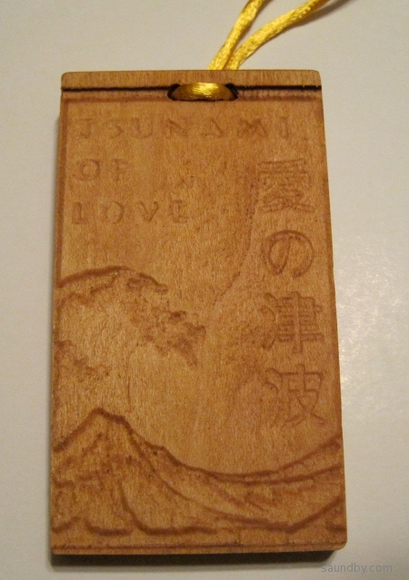
I set aside my other projects, and turned out a number of little "remembrance tablets", as you see in the pictures here. The idea was that for each one we sell, we'd pass on the profits to Second Harvest Japan, Japan's first food bank. We think they do great work, whether there's been a disaster or not. So it seemed like a good cause to support.
The tablets are about 1.5 by 2.25 inches (~3.7 x 6 cm), hung on a cord so to be worn around the neck. Each design is bilingual, English and Japanese. I took a bit of a liberty with the "Prosper" tablets, the Japanese is more properly "Prosperity" but the English word was too long to fit on the tablet with the level of detail I'm able to carve at present.


There were some other designs that I'll try to get decent photos of soon.
Unfortunately, we weren't able to sell all of these tablets, I still have many left. If you're interested, drop me an email. I have instances of all the above plus a couple of other designs available. And it'll still benefit Japan--that's what these were made for.
Making the Tohoku Remembrances
These were made using the image-to-gcode converter included with EMC2. It's got some serious quirks to its behavior I had to overcome. When I originally set out to make these, I had two ways I could do it. I considered writing my own gcode programs by hand, and using the image converter.
I decided to go with the image converter because I thought it would allow me to make more different designs faster than writing my own programs by hand. Unfortunately, I was wrong. The time I spent learning the quirks of the image converter, with what sort of feature depth I would get, how much of a border around the image, and so on was far, far more than I expected. It would have been far more productive to hand-code the simple designs I ended up with.
My original ideas were more involved, more like the "Tsunami of Love" design, above, which was carved last of all at about midnight before the con. On each iteration I ended up simplifying my designs while trying to get the sort of features I wanted in the carving. I wanted to have the Kanji characters carved into the wood, originally, but I couldn't control the way the software managed the depth and width of the lines when doing this. The Kanji would end up barely visible, and the English characters were unreadable.
A CNC Success, in a Way
I took advantage of this project as an initial test of my ability to do some small-scale production with my new CNC. As a fundraiser, I have to say it didn't work out so well, but as a first go at some small-scale, simple production it was a success--barely.
My decision to rely on someone else's software that I don't entirely understand was a real weak point, but I still managed to turn out a decent number of pieces of work before the con. The investment of time into each one was over double what I originally expected. Still, I got them done within the time margin I provided for this project. Barely.
I'm happy with the results, particularly the Tsunami of Love item, and think I could go on to make some better stuff. Though I clearly need to work on my toolchain. In the future I need to have a tool at hand that I'm familiar with that will produce better results than the free image-to-gcode converter. And I need to have something that's more powerful than hand-written gcode programs for all but the simplest designs.
I've learned a lot over the past week, both about myself and my CNC machine. Now I'm ready for the next step.
Tweet
I set aside my other projects, and turned out a number of little "remembrance tablets", as you see in the pictures here. The idea was that for each one we sell, we'd pass on the profits to Second Harvest Japan, Japan's first food bank. We think they do great work, whether there's been a disaster or not. So it seemed like a good cause to support.
The tablets are about 1.5 by 2.25 inches (~3.7 x 6 cm), hung on a cord so to be worn around the neck. Each design is bilingual, English and Japanese. I took a bit of a liberty with the "Prosper" tablets, the Japanese is more properly "Prosperity" but the English word was too long to fit on the tablet with the level of detail I'm able to carve at present.
This tablet is larger than the others, measuring 2 x 3.5 inches (5 by 9 cm). The detail is far more striking in person than in this photo where the light from overhead washes it out.
There were some other designs that I'll try to get decent photos of soon.
Unfortunately, we weren't able to sell all of these tablets, I still have many left. If you're interested, drop me an email. I have instances of all the above plus a couple of other designs available. And it'll still benefit Japan--that's what these were made for.
Making the Tohoku Remembrances
These were made using the image-to-gcode converter included with EMC2. It's got some serious quirks to its behavior I had to overcome. When I originally set out to make these, I had two ways I could do it. I considered writing my own gcode programs by hand, and using the image converter.
I decided to go with the image converter because I thought it would allow me to make more different designs faster than writing my own programs by hand. Unfortunately, I was wrong. The time I spent learning the quirks of the image converter, with what sort of feature depth I would get, how much of a border around the image, and so on was far, far more than I expected. It would have been far more productive to hand-code the simple designs I ended up with.
My original ideas were more involved, more like the "Tsunami of Love" design, above, which was carved last of all at about midnight before the con. On each iteration I ended up simplifying my designs while trying to get the sort of features I wanted in the carving. I wanted to have the Kanji characters carved into the wood, originally, but I couldn't control the way the software managed the depth and width of the lines when doing this. The Kanji would end up barely visible, and the English characters were unreadable.
A CNC Success, in a Way
I took advantage of this project as an initial test of my ability to do some small-scale production with my new CNC. As a fundraiser, I have to say it didn't work out so well, but as a first go at some small-scale, simple production it was a success--barely.
My decision to rely on someone else's software that I don't entirely understand was a real weak point, but I still managed to turn out a decent number of pieces of work before the con. The investment of time into each one was over double what I originally expected. Still, I got them done within the time margin I provided for this project. Barely.
I'm happy with the results, particularly the Tsunami of Love item, and think I could go on to make some better stuff. Though I clearly need to work on my toolchain. In the future I need to have a tool at hand that I'm familiar with that will produce better results than the free image-to-gcode converter. And I need to have something that's more powerful than hand-written gcode programs for all but the simplest designs.
I've learned a lot over the past week, both about myself and my CNC machine. Now I'm ready for the next step.
Friday, May 6, 2011
What I Learned with My CNC Machine Today
I'm in the second day of a one day project today. Hopefully I'll finish it on Day 3.
But, at each step I'm learning new and useful things.
Nonetheless, I managed to avoid anything worse than some minor marring of the surface of one work piece. It's still usable for the project.
So far, I've succeeded at using the CNC as a really complicated and finicky power planer. Unlike the first time I used a power planer, it did not throw a piece of wood across the shop at barely subsonic velocities. One piece came a bit loose in the clamp is all. I shut down the machine in time, re-clamped it, and picked up where I left off.
Tweet
But, at each step I'm learning new and useful things.
Yesterday I learned:
- There's a point where you need to stop writing gcode by hand, and use CAD/CAM.
- Doing tool compensation by hand is a real bear.
- Don't think of designs that are too much more elaborate than what you've actually made before.
Today's Lessons:
- When your test piece is MDF and your work piece is real wood, there are going to be differences.
- Grain and cutting direction matter more when using a CNC than when you route by hand, where you make all sorts of little compensations that you don't even notice.
- Just because this piece looks like the last piece you cut doesn't mean that it really is, even if it's a piece off the same stock. This can be really important when you're clamping your work down.
Nonetheless, I managed to avoid anything worse than some minor marring of the surface of one work piece. It's still usable for the project.
So far, I've succeeded at using the CNC as a really complicated and finicky power planer. Unlike the first time I used a power planer, it did not throw a piece of wood across the shop at barely subsonic velocities. One piece came a bit loose in the clamp is all. I shut down the machine in time, re-clamped it, and picked up where I left off.
Wednesday, May 4, 2011
First Attempt at Engraving an IC with my CNC
I decided to try doing a smaller, more precise job with my microCarve A4 CNC today. I took some of my GCode program from yesterday, scaled it down (fortunately I provided variables to do all that automatically for me) and added a chip number in characters that I hoped would show with the bit I'm using.
Here's what I got:

The cut widths are about 35 thousandths. Too large for the level of detail in the smaller key pattern. The single large key above is scaled three times larger than the smaller keys. The base leg length for the small keys (the smallest segment size) is 25 thousandths. So it's easy to see why it didn't quite come out.
Still, the accuracy would have been plenty good, if I'd had a sharp enough bit.
Onward and upward! :)
Tweet
Here's what I got:
My first shot at engraving an IC top. It's not really an 8085 microprocessor, it's a dead ROM I happened to have hanging around.
The cut widths are about 35 thousandths. Too large for the level of detail in the smaller key pattern. The single large key above is scaled three times larger than the smaller keys. The base leg length for the small keys (the smallest segment size) is 25 thousandths. So it's easy to see why it didn't quite come out.
Still, the accuracy would have been plenty good, if I'd had a sharp enough bit.
Onward and upward! :)
Learning GCode with EMC2
I'm spending a lot of time with my new microCarve A4 CNC router this week. My first couple of items were made using a handy image to gcode converter that's built into the EMC2 control software I'm using.
But the image converter simply treats the image as a depth map which is cut by raster-scanning with the cutting head. For the designs I used, this was slow, and produced rougher results than would be produced using vector cuts.
So I looked at a couple of approaches to improve things. One is using CAD software that works well with a CAM package to covert the CAD design into machine control instructions to cut out the CAD shapes. The other is to go straight to writing my own machine control programs by hand. I know that I'll want to have both methods in my toolkit, but which to use first?
After a bit of back and forth yesterday morning, I decided to start with programming by hand first. So I dove into the EMC2 documentation for gcode, the programming language more properly called RS-274-NGC. What a catchy name, eh? You can bet that the folks who picked programming language names like "python" and "Java" are kicking themselves after seeing how "RS-274-NGC" rolls off the tongue.

Well, the EMC2 site has a link for a gcode tutorial, but what's there is...not much. Maybe I'll pitch in, since that's what wikis are for, right? The I went an read the EMC2 documentation, which has the standard cart-before-horse format of discussing details before generalities. Then I found the excellent LumenLabs GCode Tutorial. Much better!
I read some bits, scanned others, then hit the keyboard on my CNC control system. It's an old Athlon 800 with 768MB of RAM loaded up with the EMC2 LiveCD install for Ubuntu Hardy Heron, with EMC2 upgraded to the current version after install.
I fired up EMC2 with the SIM-Axis configuration for developing the gcode. I've got three different configurations of EMC2 on my desktop. I've got the SIM-Axis setup, and two different configurations for my microCarve A4, each with different origins for the axes.
I used gedit to create an initial gcode file, then opened it in EMC2. The gcode preview window is great. Whenever I edited the gcode file and saved, I'd click the reload button in EMC2 and immediately see the changes. Likewise, the error messages were good enough to let me find my problems, though the problems were usually typos rather than what was reported.
I used iterative development, of course. No sense writing too much code before finding out that I didn't understand some element of syntax. I started with initializing the mode settings, lifting the head to a safe traversal height, traversing to a point in space, then returning to machine zero. After fixing a couple of problems, I got what I wanted. Then I added a few additional move commands, and got the simulated CNC to follow them. At that point I could see that things would get out of hand pretty quick if I didn't learn some basic flow control.
So I read up on subroutines in gcode. I laid out a simple key pattern on graph paper, and wrote the necessary routines. That's the border you see in the picture above. That was the easy part. It's all straight lines.
Next was curves. I read up on G2 and G3. I hadn't thought about the ability to shift the depth of cut across the curve when I started reading, but by the time I was done I was thinking, "Hmmm, if I vary the depth of the cut with a V groove bit, I can vary the width of the cut just as I would vary the width of a line with a calligraphy pen."
So I broke out a fresh sheet of graph paper, and started drawing some letters. Well, it took me about three times as long to lay out the letters as it took me to lay out the key pattern, but I managed that. Not only that, but I set things up with scaling factors and variable settings that allow me to easily scale and move the letters.
Results
The results you see above are what I got from the first "live" run of my first gcode program. The cuts are a bit deeper than I'd like, and the 90 degree bit I'm using right now doesn't help. Also, the cutting was a bit fast for the plywood, causing the wood to be frayed on the cross-grain cuts. Still, the varying of "line weight" on the letters turned out well. Overall I'm happy with it, and the defects should be easy to fix when I run it again. I'm planning on building a complete alphabet for this font and throwing it into a file for later use.
Tweet
But the image converter simply treats the image as a depth map which is cut by raster-scanning with the cutting head. For the designs I used, this was slow, and produced rougher results than would be produced using vector cuts.
So I looked at a couple of approaches to improve things. One is using CAD software that works well with a CAM package to covert the CAD design into machine control instructions to cut out the CAD shapes. The other is to go straight to writing my own machine control programs by hand. I know that I'll want to have both methods in my toolkit, but which to use first?
After a bit of back and forth yesterday morning, I decided to start with programming by hand first. So I dove into the EMC2 documentation for gcode, the programming language more properly called RS-274-NGC. What a catchy name, eh? You can bet that the folks who picked programming language names like "python" and "Java" are kicking themselves after seeing how "RS-274-NGC" rolls off the tongue.
Results of My First GCode Program.
Well, the EMC2 site has a link for a gcode tutorial, but what's there is...not much. Maybe I'll pitch in, since that's what wikis are for, right? The I went an read the EMC2 documentation, which has the standard cart-before-horse format of discussing details before generalities. Then I found the excellent LumenLabs GCode Tutorial. Much better!
I read some bits, scanned others, then hit the keyboard on my CNC control system. It's an old Athlon 800 with 768MB of RAM loaded up with the EMC2 LiveCD install for Ubuntu Hardy Heron, with EMC2 upgraded to the current version after install.
I fired up EMC2 with the SIM-Axis configuration for developing the gcode. I've got three different configurations of EMC2 on my desktop. I've got the SIM-Axis setup, and two different configurations for my microCarve A4, each with different origins for the axes.
I used gedit to create an initial gcode file, then opened it in EMC2. The gcode preview window is great. Whenever I edited the gcode file and saved, I'd click the reload button in EMC2 and immediately see the changes. Likewise, the error messages were good enough to let me find my problems, though the problems were usually typos rather than what was reported.
I used iterative development, of course. No sense writing too much code before finding out that I didn't understand some element of syntax. I started with initializing the mode settings, lifting the head to a safe traversal height, traversing to a point in space, then returning to machine zero. After fixing a couple of problems, I got what I wanted. Then I added a few additional move commands, and got the simulated CNC to follow them. At that point I could see that things would get out of hand pretty quick if I didn't learn some basic flow control.
So I read up on subroutines in gcode. I laid out a simple key pattern on graph paper, and wrote the necessary routines. That's the border you see in the picture above. That was the easy part. It's all straight lines.
Next was curves. I read up on G2 and G3. I hadn't thought about the ability to shift the depth of cut across the curve when I started reading, but by the time I was done I was thinking, "Hmmm, if I vary the depth of the cut with a V groove bit, I can vary the width of the cut just as I would vary the width of a line with a calligraphy pen."
So I broke out a fresh sheet of graph paper, and started drawing some letters. Well, it took me about three times as long to lay out the letters as it took me to lay out the key pattern, but I managed that. Not only that, but I set things up with scaling factors and variable settings that allow me to easily scale and move the letters.
Results
The results you see above are what I got from the first "live" run of my first gcode program. The cuts are a bit deeper than I'd like, and the 90 degree bit I'm using right now doesn't help. Also, the cutting was a bit fast for the plywood, causing the wood to be frayed on the cross-grain cuts. Still, the varying of "line weight" on the letters turned out well. Overall I'm happy with it, and the defects should be easy to fix when I run it again. I'm planning on building a complete alphabet for this font and throwing it into a file for later use.
Subscribe to:
Posts (Atom)


 Posts
Posts


 Webomator.com: Backward into the