
Showing posts with label microcontroller. Show all posts
Showing posts with label microcontroller. Show all posts
Tuesday, April 22, 2014
Clearance on Propellor Quickstart Boards at Radio Shack!
Monday, January 6, 2014
Parallel Processes on the XMOS StartKIT

XMOS sent me a free StartKIT development board just in time for Christmas. Now that the festivities are over, I've had a chance to get started with it. It's a bit frustrating because XMOS's documentation has the necessary information scattered rather broadly, and documents that you'd expect to contain certain pieces of information do not.* It's all there, just poorly organized & often hidden in long documents where you wouldn't expect it.
That said, the hardware is exciting in its potential. Once I got through the basic tutorial stuff I went to write a simple multiprocessing program--handing over the blinking of two LEDs on the board to two independent processes.
Here again I ran into documentation deficiencies. XMOS presents code examples in their docs as snippets, not full programs. This leads to misunderstandings due to lack of context. I was able to get a program going, on the third attempt. The first syntax I tried created two dependent processes. The second's syntax was not accepted even though it was copied from a sample snippet--it had a variable that needed to be declared, but I didn't know what type to declare it as, and the declarations are left out of the snippets. The third try worked, but only after enough time spent reading and time spent doing some fortunate guesswork to have gotten a lot further with another, better documented hardware platform.
Lighting a Candle While Cursing the Darkness
I still think this is the right platform for the initial ideas I had for it, though. So as I press on, step by step, in implementing those ideas, I'm going to document what I learn & hope to save others time and trouble. I've made a couple of resolutions about the code, similar to those on the code for my Begin with Java blog:
1. All examples will be presented as complete, compilable programs.
2. All examples will use multiprocessing syntax and structure.
Look for this code to appear on my website, saundby.com soon.
Until then:Don't follow the example syntax XMOS uses of writing your code inside main(). All main() should contain is channel declarations and par{} blocks. Put all your code into functions to be called inside par{} blocks.
The code for the dual process LED blinker:
/*
 * LED Tests.xc
 *
 *  Created on: Jan 5, 2014
 *      Author: saundby
 */
#include <xs1.h>

out port    p1              =   XS1_PORT_1A;    //PORT 1A for D1 LED
out port    p2              =   XS1_PORT_1D;    //PORT 1D for D2 LED

void led1(){
    while(1){ //run forever
        p1 <: 1; // LED D1 On
        delay_milliseconds(200);
        p1 <: 0; // LED D1 Off
        delay_milliseconds(200);
    }
}

void led2(){
    while(1){ // run forever
        p2 <: 0; // LED D2 Off
        delay_milliseconds(50);
        p2 <: 1; // LED D2 On
        delay_milliseconds(350);
    }
}

int main(void) {
    // Note: put the 'forever' loop in each of the
    // individual tasks, not out here.
   par{
       led1();
       led2();
   }
   return 0;
}
* It took me forever to find the electrical characteristics of the I/Os in the data sheets, but they are there. There just isn't a data sheet for the specific IC used in the StartKIT, which is a unique item not for sale separately. Personally, I consider it a major oversight to not either provide a data sheet for this specific IC or to include that information in the Hardware Manual for the StartKIT. Based on the scuttlebutt in the forums, I'm using the datasheet for the XS1-A8A-64-FB96 (PDF) as the closest analogue.
Wednesday, August 15, 2012
Parallax Propeller + COSMAC 1802: the Saga Continues...
Monday morning I posted about hooking up a Parallax Propeller QuickStart Board to an 1802 Microprocessor. My hopes are to make the Propeller behave as a RAM for the 1802, primarily to be able to display a bitmap of that segment of memory as video. The idea is to make it compatible software-wise with the 1861 Pixie chip (the 1802's native video adapter), which is presently unavailable.
Since then I've spent more time on this project. A lot of that time got tied up in side issues related to tying a Propeller to an 1802, as well as some time spent dealing with the test equipment I want to use to keep an eye on the circuit and see what it's up to.
First, here's how it looks tonight:

Clocking the 1802
One thing I put a fair bit of time into (too much, that is) is using the Propeller to control the clock of the 1802. There are a few reasons I think this would be nice:
The clock can be varied in software depending on the user's desire and the individual 1802's capabilities.
At some later point, the Prop can have a greater degree of control over the 1802's operation in general. With the ability to stop it, start it, and even single-step it.
On my first stab at this a couple of days ago, I just threw a repeat loop into the Prop's code to pulse an output line. I didn't have very good control of the rate, I didn't have the constants set right, and it didn't work right off the bat so I decided to drop it and just use another clock.
Let's Try a Timer, Because...That's What They're For
This time I took time to read up on using the counter/timers on the Prop. Each cog has one, and I played around with it for a while before feeding its output to the 1802's clock input. After a while I was able to get the results I wanted, and was able to fine-tune that bit of the code.
Then I hooked it up to the 1802 with a frequency of 1.25MHz...well, I should say I hooked it up to a 4049, passed it through a pair of inverters to square it up a bit and buffer it. Then I passed the signal to the 1802. Which ran just fine.
At this point I still had the data bus of the 1802 hard wired to a $C4, which is a NOP instruction for the 1802. That way I can watch LEDs on the address bus and see that the chip is running through its address space. The pulse rate of the high order LED gives me an immediate idea of how fast the 1802 is getting clocked, too.
Then I started playing with the constant for the counter's frequency to see what speeds this 1802 chip would be good at with a 5V Vdd and 3.3V Vcc (the 1802 can use split supply voltages for its core and I/O. Not bad for 1976, eh?)
Overclocking! 4.8MHz Baby! Yeah, uh, Megahertz.
This one ran up to 3.6MHz without a problem. I didn't run it up until it stopped, the other day I think I had it running at about 4MHz when I was playing with the repeat loop. Above 3.6MHz it seemed to start running hot, so I stepped it back down again.
Above 3.6MHz it was noticeably warm after a while, and seemed to be getting warmer. Between 3.2 and 3.6MHz it was warm, but maintaining its temperature just fine. At 3.2MHz it was solid as a rock and the heat was barely detectable to a calibrated fingertip. If I can get it to run at this speed reliably with the Propeller providing video then popular Elf software like Tiny Basic, Forth, CHIP-8, and the programs written in them are going to rock on this system.
Edit: I've run it up to 4.807MHz now, and it didn't seem all that hot this time. It really shouldn't have any problem with heat at these voltages, it normally runs at 5MHz at higher voltages. And now it doesn't seem to have a problem. When I tried to take it over 4.8MHz it ran sometimes but not others, or hung occasionally. So this is the limit for stable operation at this voltage for this chip (an RCA CDP1802CE.)
Getting Data to the 1802
OK, so back to the problem of making the Propeller look like a RAM. Frankly, when I did my first look at the timing involved, I figured this would be completely trivial to implement. Push in data and address bus wires, connect up /MRD (memory read signal) from the 1802 to the Prop, crank a little Spin code, and I'd have the Prop acting like a ROM.
Put in /MWR and a little more code, BAM, the Prop is a RAM.
Hook up TPA to catch the high order address byte, tweak the code, and the Prop is ready to map more than 256 bytes. All I'd have to do is add the video code then figure out how much Prop RAM was available then expand to fit.
Well, it wasn't that easy. If it had been, I'd be playing with the video now.
I tried to leap forward at first. I plugged in the address and data bus wires, plugged in /MRD, and added some code to my clock driver program. It had a 256 byte array that it set up and initialized to $C4 in every position (NOP again, but this time it would be a soft NOP rather than a hard-wired one.) Then I wrote the program to wait for the Propeller I/O line I'd selected for /MRD to go low. Once that happened, it would get the address off the address bus, look up the appropriate element in the RAM array in memory, and put it out on the data bus until /MRD came back up again.
Easy-peasy, right?
Well, it didn't work.

When I was doing my timing calcs and looking at the 1802's leisurely timing--it doesn't mind waiting just under a millisecond for its memory to come back when it's running at its normal speed (about 1.78MHz.) Hey, an 80MHz processor could be running a version of interpreted BASIC written in LISP and keep up with that, right?
I guess not. At least not the way I did it.
I clocked the 1802 at 1.25MHz for the test. This is an easy, slow speed that the Propeller can generate easily. I figured it'd work, I'd push up the frequency to 2.5MHz, check timings on the scope, and discover that I couldn't make the 1802 go too fast for the Prop.
Unfortunately the trace above shows different.
I Can Do Lots of Things Wrong, All at Once
I'm sure this is the result of something I'm doing improperly. I can think of several possibilities already:
I'm using WAITPNE and WAITPEQ to respond to the pin change. Perhaps, because they do some power-saving activity on the cog on which they're invoked, they just aren't meant to respond this quickly. Maybe if I just go to an active polling loop I'll be OK?
I'm using SPIN, an interpreted language. Perhaps I need to just insert a bit of Propeller assembly to tighten up the timing?
Perhaps there's some option or configuration thing I've not done?
Maybe this cog has to do something active with the timer/counter (I'm using the same cog as the one that's running the 1802's clock.) Perhaps if I move the RAM functions to another cog I'll be fine?
Those are just what comes off the top of my head. I'm far from being an expert on the Propeller, and I haven't picked up the books on it yet, just the free manual and datasheet downloads. But things like this create an opportunity to learn.
I also had a few other things I needed to figure out on the way, minor little things like the order you mention the output pins in when writing your code statements (I was getting $23 out instead of $C4 initially. Yeah, oops.) That and the whole thing is a rather fragile lash-up right now. I'm going to go to solder as soon as I get the RAM moving data to and from the 1802. But not before, because I hate rework, and if I don't test it on a breadboard first, there'll be rework. And this lets me do a few things like change which lines I'm using for address and data easily. I moved the data lines to P16..23 so that I can watch the data on the QuickStart board's LEDs, like a little front panel. Before, I had the address lines here, but I've already got LEDs on the breadboard showing me the address line states. So a quick change of a few constants in software, and I get a data display with no re-soldering.
Slightly Off-Task Tasks
I also took some time out to search out a line cord for the new frequency counter I got at the Ham Radio Club night before last that didn't have one (found one, after searching high and low. It's an oddball, not an HP cord.) And I checked out the two portable NonLinear Systems oscilloscopes I bought, too (one works, one doesn't, as expected.) The frequency counter was very nice to have while I was figuring out how to use the Prop's counter/timer as a numerically controlled oscillator, so the time was well spent even if it did eat into my Propeller-as-RAM time.
Looking Forward to Round 3
I'll be back at this before the end of the week (I'd like to tomorrow, but it'll be a busy day so I may not be able to.) If you have any suggestions or salient experience, your comments or emails would be much appreciated!
Edit:
I've had a look at the Propeller docs. It looks like the timing of hub instructions is my problem. I may just insert WAIT states for the 1802 and see what that does.
Tweet
Since then I've spent more time on this project. A lot of that time got tied up in side issues related to tying a Propeller to an 1802, as well as some time spent dealing with the test equipment I want to use to keep an eye on the circuit and see what it's up to.
First, here's how it looks tonight:

The second stage of the Propeller/1802 mashup circuit. Click for full size.
Clocking the 1802
One thing I put a fair bit of time into (too much, that is) is using the Propeller to control the clock of the 1802. There are a few reasons I think this would be nice:
The clock can be varied in software depending on the user's desire and the individual 1802's capabilities.
At some later point, the Prop can have a greater degree of control over the 1802's operation in general. With the ability to stop it, start it, and even single-step it.
On my first stab at this a couple of days ago, I just threw a repeat loop into the Prop's code to pulse an output line. I didn't have very good control of the rate, I didn't have the constants set right, and it didn't work right off the bat so I decided to drop it and just use another clock.
Let's Try a Timer, Because...That's What They're For
This time I took time to read up on using the counter/timers on the Prop. Each cog has one, and I played around with it for a while before feeding its output to the 1802's clock input. After a while I was able to get the results I wanted, and was able to fine-tune that bit of the code.
Then I hooked it up to the 1802 with a frequency of 1.25MHz...well, I should say I hooked it up to a 4049, passed it through a pair of inverters to square it up a bit and buffer it. Then I passed the signal to the 1802. Which ran just fine.
At this point I still had the data bus of the 1802 hard wired to a $C4, which is a NOP instruction for the 1802. That way I can watch LEDs on the address bus and see that the chip is running through its address space. The pulse rate of the high order LED gives me an immediate idea of how fast the 1802 is getting clocked, too.
Then I started playing with the constant for the counter's frequency to see what speeds this 1802 chip would be good at with a 5V Vdd and 3.3V Vcc (the 1802 can use split supply voltages for its core and I/O. Not bad for 1976, eh?)
Overclocking! 4.8MHz Baby! Yeah, uh, Megahertz.
This one ran up to 3.6MHz without a problem. I didn't run it up until it stopped, the other day I think I had it running at about 4MHz when I was playing with the repeat loop. Above 3.6MHz it seemed to start running hot, so I stepped it back down again.
Above 3.6MHz it was noticeably warm after a while, and seemed to be getting warmer. Between 3.2 and 3.6MHz it was warm, but maintaining its temperature just fine. At 3.2MHz it was solid as a rock and the heat was barely detectable to a calibrated fingertip. If I can get it to run at this speed reliably with the Propeller providing video then popular Elf software like Tiny Basic, Forth, CHIP-8, and the programs written in them are going to rock on this system.
Edit: I've run it up to 4.807MHz now, and it didn't seem all that hot this time. It really shouldn't have any problem with heat at these voltages, it normally runs at 5MHz at higher voltages. And now it doesn't seem to have a problem. When I tried to take it over 4.8MHz it ran sometimes but not others, or hung occasionally. So this is the limit for stable operation at this voltage for this chip (an RCA CDP1802CE.)
Getting Data to the 1802
OK, so back to the problem of making the Propeller look like a RAM. Frankly, when I did my first look at the timing involved, I figured this would be completely trivial to implement. Push in data and address bus wires, connect up /MRD (memory read signal) from the 1802 to the Prop, crank a little Spin code, and I'd have the Prop acting like a ROM.
Put in /MWR and a little more code, BAM, the Prop is a RAM.
Hook up TPA to catch the high order address byte, tweak the code, and the Prop is ready to map more than 256 bytes. All I'd have to do is add the video code then figure out how much Prop RAM was available then expand to fit.
Well, it wasn't that easy. If it had been, I'd be playing with the video now.
I tried to leap forward at first. I plugged in the address and data bus wires, plugged in /MRD, and added some code to my clock driver program. It had a 256 byte array that it set up and initialized to $C4 in every position (NOP again, but this time it would be a soft NOP rather than a hard-wired one.) Then I wrote the program to wait for the Propeller I/O line I'd selected for /MRD to go low. Once that happened, it would get the address off the address bus, look up the appropriate element in the RAM array in memory, and put it out on the data bus until /MRD came back up again.
Easy-peasy, right?
Well, it didn't work.

Top: Data from Propellor pretending to be a memory. Bottom: Memory Read Request. Result: Memory Too Slow! (Click for full size.)
When I was doing my timing calcs and looking at the 1802's leisurely timing--it doesn't mind waiting just under a millisecond for its memory to come back when it's running at its normal speed (about 1.78MHz.) Hey, an 80MHz processor could be running a version of interpreted BASIC written in LISP and keep up with that, right?
I guess not. At least not the way I did it.
I clocked the 1802 at 1.25MHz for the test. This is an easy, slow speed that the Propeller can generate easily. I figured it'd work, I'd push up the frequency to 2.5MHz, check timings on the scope, and discover that I couldn't make the 1802 go too fast for the Prop.
Unfortunately the trace above shows different.
I Can Do Lots of Things Wrong, All at Once
I'm sure this is the result of something I'm doing improperly. I can think of several possibilities already:
I'm using WAITPNE and WAITPEQ to respond to the pin change. Perhaps, because they do some power-saving activity on the cog on which they're invoked, they just aren't meant to respond this quickly. Maybe if I just go to an active polling loop I'll be OK?
I'm using SPIN, an interpreted language. Perhaps I need to just insert a bit of Propeller assembly to tighten up the timing?
Perhaps there's some option or configuration thing I've not done?
Maybe this cog has to do something active with the timer/counter (I'm using the same cog as the one that's running the 1802's clock.) Perhaps if I move the RAM functions to another cog I'll be fine?
Those are just what comes off the top of my head. I'm far from being an expert on the Propeller, and I haven't picked up the books on it yet, just the free manual and datasheet downloads. But things like this create an opportunity to learn.
I also had a few other things I needed to figure out on the way, minor little things like the order you mention the output pins in when writing your code statements (I was getting $23 out instead of $C4 initially. Yeah, oops.) That and the whole thing is a rather fragile lash-up right now. I'm going to go to solder as soon as I get the RAM moving data to and from the 1802. But not before, because I hate rework, and if I don't test it on a breadboard first, there'll be rework. And this lets me do a few things like change which lines I'm using for address and data easily. I moved the data lines to P16..23 so that I can watch the data on the QuickStart board's LEDs, like a little front panel. Before, I had the address lines here, but I've already got LEDs on the breadboard showing me the address line states. So a quick change of a few constants in software, and I get a data display with no re-soldering.
Slightly Off-Task Tasks
I also took some time out to search out a line cord for the new frequency counter I got at the Ham Radio Club night before last that didn't have one (found one, after searching high and low. It's an oddball, not an HP cord.) And I checked out the two portable NonLinear Systems oscilloscopes I bought, too (one works, one doesn't, as expected.) The frequency counter was very nice to have while I was figuring out how to use the Prop's counter/timer as a numerically controlled oscillator, so the time was well spent even if it did eat into my Propeller-as-RAM time.
Looking Forward to Round 3
I'll be back at this before the end of the week (I'd like to tomorrow, but it'll be a busy day so I may not be able to.) If you have any suggestions or salient experience, your comments or emails would be much appreciated!
Edit:
I've had a look at the Propeller docs. It looks like the timing of hub instructions is my problem. I may just insert WAIT states for the 1802 and see what that does.
Monday, August 13, 2012
Parallax Propeller + Cosmac Elf = ?
I've started working on one implementation of an idea I've had for a while...
There's this neat old 70's computer system called the COSMAC Elf. It's like a lot of the microprocessor trainer systems of the time, but it's got some unique abilities that make it a bit more interesting to build, and expand on, than some of the others.
Video output being one of the biggies.
Step One
Before I go further, here's a look at an early step in implementing my idea:

Here I've gotten to the point of getting clock and two levels of power from the Quickstart board to the 1802 CPU. First, I had a crystal oscillator circuit providing a clock to the 1802. Only 5V power came from the Vin on the Quickstart board.
Then, I split the voltages. The crystal oscillator, the inverter for the clock signal, and Vdd for the 1802 were split off with 5V power, and the rest of the circuit was put on the 3.3V power from the Quickstart board. At this point, I'd been running the 1802 at 1MHz, slow enough I could easily watch the LEDs on the address lines changing as it ran.
Then I moved up to a 2MHz oscillator. The 1802 was still good with that, with its Vdd at 5V and Vcc at 3.3V.
Then I tried to get fancy.
I took an output off the Prop and tried to use a repeat-wait structure to clock the 1802. It worked, up to a point. But I got to where I was unsure of my actual frequency, and the 1802 stopped running at a slower speed than I expected (I thought.) In fact, I was getting too clever and messing myself up. Looking back, I was probably somewhere above 4MHz when the 1802 refused to run any more!
After a while I realized that, and just decided to put the crystal oscillator back in.
Then I took another look, and decided that a 5MHz XI off of the QS board could be used as a clock base. A 2.5MHz clock would be fine (actually, anything from 1.76MHz on up would be fine.) Most Elf computers run somewhere around 1.76 to 1.79MHz to accommodate the clock for the video IC they use. Getting at least that speed is pretty much a must for me to feel like this project is going where I want it to. But getting a faster clock would be even better, as we'll see.
First I dropped in a CMOS part--a 4013--to act as a divider for the 5MHz clock to drop it to 2.5MHz for the 1802. I forgot that at 5V the 4013 only really works up to 4MHz on its input. So that turned out to be a waste of time.
Then I dug out a small supply of 74AC74 ICs, which work fine at well 5MHz and above. It worked fine, dividing the 5MHz down to 2.5MHz. In fact, just to be a little conservative, I used both flip flops to divide the clock down to 1.25MHz, then ran that to the inverter I'd had the crystal oscillator going to.
That worked, so I tried the 2.5MHz output. At first the 1802 wouldn't run, I pushed the Reset switch, and noticed the clock took off when I bumped the Ground wire. Once the ground wire was back in its place securely, the 1802 ran just fine at 2.5MHz.
Then I bypassed the 4049 inverter, the signal from the 74AC74 is plenty strong enough to drive the 1802 by itself.
That was step one. Time for a break before step two.
The Plan
So why hook up an old CPU to a fast modern CPU like the Propeller?
Because of a problem with getting chips for the old Elf computer.
People still like building the old Elf computer. It's a complete computer system that can be built in an afternoon if you've got all the parts and tools at hand (I built my first in about four hours.) It's a computer that pretty well exposes all of its parts to examination, so it's easy to learn how it works, and to understand all the bits of the system.
The video IC, called the CDP1861 Pixie chip, is one of the simplest video ICs ever made. It's basically some timing and control signals wrapped around a shift register that works with the DMA mode of the 1802 to produce a really nifty one chip video interface.
It's not exactly workstation graphics, being monochrome with resolutions ranging from 64 x 32 to 64 x 128. But it does the job. People program the system using this quality of video. And you thought the Vic-20 was low-res!
Well, the problem is that in the past few years Pixie chips have pretty well become Unobtanium (a term that goes way back before the movie Avatar, by the way.) In other words, you can't get 'em. There have been a couple of less than optimal replacements (from the perspective of new ELf builders who have to make them up themselves rather than just buy one pre-made.)
I'm trying to come up with something slightly less suboptimal. And solve a problem that the Pixie chip has.
The Third Cycle...of DOOM
The Pixie's problem is that its timing only deals well with 1802 programs that use instructions that take two instruction cycles or less to complete. There are two instructions, Long Branch and Long Skip, that take 3 cycles. They create jitter in the video by throwing its timing off.
Since the Elf's video is basically just a straight bitmap of a chunk of memory on the screen (the lowest resolution, 64 x 32, is a map of the Elf's base 256 Bytes of memory straight to video.) So, if some other circuit could just read a relatively new, fast RAM in the time when the 1802 isn't reading it, then the other circuit could just pull the data then run it to video, and leave the Elf none the wiser.
That way all the Elf has to do is manipulate the data in the section of memory on the screen. And a 3-cycle instruction won't cause any problems. And the 1802 gets about 40% of its time back, during which it would otherwise have been doing DMA of that memory data to the Pixie chip's shift register.
So:
Video that doesn't need the unobtainable Pixie,
No 3-cycle instruction timing issues,
No loss of 40% processing time to video DMA, and
Able to run at higher clock speeds.
Sounds like a winner, right?
Implementation Details
Next was how to actually implement it. I've looked at several ways, with various advantages and disadvantages.
Using faster RAMs was a first building block I looked at. For example, a static RAM pulled out of a 486 motherboard's cache RAM would be more than fast enough. Both 20nS and 15nS are readily available. Plenty fast to grab a byte once every 1802 instruction cycle for the external video system.
Then, came my initial thought, maybe use an Atmel AVR microcontroller to do the grabbing, put the data into its internal RAM, use that as a frame buffer for some bit-bashed monochrome video. No big deal.
No big deal if you've already got the ability to program AVRs or are prepared to supply them preprogrammed. Still, not a bad solution. Just not likely to be popular as I'd like because of the hurdle of programming the chip. The idea wasn't just considered with an AVR, any of a number of uC families could work. But they had the same problem.
Another idea was to build a circuit from random logic. Not as appealing, with my schedule, but if I could be the pioneer on this and put something together then anyone could order the parts and start wiring. It would probably add about 1/3 to double the work to assembling an Elf computer. Again, not perfect, but possible.
Then I thought about taking the AVR idea and putting in a Propeller board. The advantage here is that, rather than getting a bare microcontroller and having to get the infrastructure to program it to do the One Job that that user may ever use it for, the board itself is all the infrastructure needed. (Yes, Arduino occurred to me, too.)
A download on a computer, a USB cable of the correct type (I'm using a cell phone charging cable), and you're in business. Even if the user never does anything with a Propeller again (what an unfortunate thought!) then they wouldn't be out anything but a bit of their time to get the "part" they need programmed for the job.
And it's less time than hand-wiring random logic on a perf board, no matter how you look at it.
It Just Keeps Getting Better
So, I started with the idea that the speedy (80MHz) Propeller would have no problem sneaking in and reading bytes out of the Elf's RAM during those long, lazy ~200nS slack periods. Then it could put the data into an internal frame buffer.
And, what hey!, the Propeller has built-in video. I could make it so that the final Propellor program puts out Composite baseband, Composite broadcast, and VGA all at once. What a deal! The user doesn't even have to pick between different programs based on what sort of video they want right now.
Then came the next idea. Replace a chunk of the Elf's RAM entirely. Let the Propeller be a chunk of RAM.
It can't replace all the possible RAM of an Elf in its present version. It's only got 32K of RAM in it, and it needs some of that for any applications it's running.
But, it can replace a chunk of the Elf's RAM. Enough for Pixie-quality video. And with some lines used for control, the video resolution and frame buffer location within that memory can be changed. I don't know yet, but it seems like mapping somewhere from 2K to 4K wouldn't be that difficult.
Pixie Compatibility
At first, I'm going to concentrate on a limited memory map, and on replicating the basic Pixie mode of 64 across by 32 high. In spite of the fact that there won't be any actual DMA transfer needed, it should be able to display video from the basic Pixie video programs like the iconic Starship Enterprise video from 1977 without modification. They'll just run faster as a result of no DMA overhead. I think.
Then looking at the exact details of how an expanded Elf uses the other modes (if it does, I've never done so myself) will let me look at expanding the Propeller's memory map area and responding to the Elf's control to do that.
So, if I can do what the Pixie does without requiring DMA, I'm already getting a system that's about 40% faster even if I don't move up the clock speed from ~1.79MHz. (The 1802 was the original overclocker's chip, way back in the 70's, but that's another story.) If I can increase the clock speed even more, with no effect on the video (since a hard-clocked Pixie chip isn't there any more), then I've got a system that'll run such things as Chip-8 and Tiny Basic that much faster than an original Elf with a Pixie.
If the 2.5MHz setup turns out to work (I see no obstacles at present, but that just means I haven't run into them yet), then I'm getting a system that should run about 2.3x faster than the stock Elf. It'll still be no speed demon (that's not the point), but it'll be nicer to use.
Next Steps, Baby Steps
I'm going to write a program for the Prop to make it pretend to be a RAM for the 1802. It will be a simple 256 byte memory. That avoids the multiplexed signals for the address. It'll (hopefully) receive and store data bytes from the 1802, and deliver data from its store on request.
The first pass is going to be really, really simple. I'm going to set up an array, put in a short program to blink an LED on the 1802's 'Q' output, and set it up to respond to the 1802's memory read requests. No writes required. If that works, then I'll add write capability and put in a program to test that (again using Q as an output.)
If that works, I'll proceed to give the 1802 some more sophisticated output and input capability and see where it goes from there. But best not to plan in too detailed a fashion too far ahead until the immediate problems are solved.
Tweet
There's this neat old 70's computer system called the COSMAC Elf. It's like a lot of the microprocessor trainer systems of the time, but it's got some unique abilities that make it a bit more interesting to build, and expand on, than some of the others.
Video output being one of the biggies.
Step One
Before I go further, here's a look at an early step in implementing my idea:

A first step: Power and Clock from the QS Board to the 1802. (Click for bigger image.)
Here I've gotten to the point of getting clock and two levels of power from the Quickstart board to the 1802 CPU. First, I had a crystal oscillator circuit providing a clock to the 1802. Only 5V power came from the Vin on the Quickstart board.
Then, I split the voltages. The crystal oscillator, the inverter for the clock signal, and Vdd for the 1802 were split off with 5V power, and the rest of the circuit was put on the 3.3V power from the Quickstart board. At this point, I'd been running the 1802 at 1MHz, slow enough I could easily watch the LEDs on the address lines changing as it ran.
Then I moved up to a 2MHz oscillator. The 1802 was still good with that, with its Vdd at 5V and Vcc at 3.3V.
Then I tried to get fancy.
I took an output off the Prop and tried to use a repeat-wait structure to clock the 1802. It worked, up to a point. But I got to where I was unsure of my actual frequency, and the 1802 stopped running at a slower speed than I expected (I thought.) In fact, I was getting too clever and messing myself up. Looking back, I was probably somewhere above 4MHz when the 1802 refused to run any more!
After a while I realized that, and just decided to put the crystal oscillator back in.
Then I took another look, and decided that a 5MHz XI off of the QS board could be used as a clock base. A 2.5MHz clock would be fine (actually, anything from 1.76MHz on up would be fine.) Most Elf computers run somewhere around 1.76 to 1.79MHz to accommodate the clock for the video IC they use. Getting at least that speed is pretty much a must for me to feel like this project is going where I want it to. But getting a faster clock would be even better, as we'll see.
First I dropped in a CMOS part--a 4013--to act as a divider for the 5MHz clock to drop it to 2.5MHz for the 1802. I forgot that at 5V the 4013 only really works up to 4MHz on its input. So that turned out to be a waste of time.
Then I dug out a small supply of 74AC74 ICs, which work fine at well 5MHz and above. It worked fine, dividing the 5MHz down to 2.5MHz. In fact, just to be a little conservative, I used both flip flops to divide the clock down to 1.25MHz, then ran that to the inverter I'd had the crystal oscillator going to.
That worked, so I tried the 2.5MHz output. At first the 1802 wouldn't run, I pushed the Reset switch, and noticed the clock took off when I bumped the Ground wire. Once the ground wire was back in its place securely, the 1802 ran just fine at 2.5MHz.
Then I bypassed the 4049 inverter, the signal from the 74AC74 is plenty strong enough to drive the 1802 by itself.
That was step one. Time for a break before step two.
The Plan
So why hook up an old CPU to a fast modern CPU like the Propeller?
Because of a problem with getting chips for the old Elf computer.
People still like building the old Elf computer. It's a complete computer system that can be built in an afternoon if you've got all the parts and tools at hand (I built my first in about four hours.) It's a computer that pretty well exposes all of its parts to examination, so it's easy to learn how it works, and to understand all the bits of the system.
The video IC, called the CDP1861 Pixie chip, is one of the simplest video ICs ever made. It's basically some timing and control signals wrapped around a shift register that works with the DMA mode of the 1802 to produce a really nifty one chip video interface.
It's not exactly workstation graphics, being monochrome with resolutions ranging from 64 x 32 to 64 x 128. But it does the job. People program the system using this quality of video. And you thought the Vic-20 was low-res!
Well, the problem is that in the past few years Pixie chips have pretty well become Unobtanium (a term that goes way back before the movie Avatar, by the way.) In other words, you can't get 'em. There have been a couple of less than optimal replacements (from the perspective of new ELf builders who have to make them up themselves rather than just buy one pre-made.)
I'm trying to come up with something slightly less suboptimal. And solve a problem that the Pixie chip has.
The Third Cycle...of DOOM
The Pixie's problem is that its timing only deals well with 1802 programs that use instructions that take two instruction cycles or less to complete. There are two instructions, Long Branch and Long Skip, that take 3 cycles. They create jitter in the video by throwing its timing off.
Since the Elf's video is basically just a straight bitmap of a chunk of memory on the screen (the lowest resolution, 64 x 32, is a map of the Elf's base 256 Bytes of memory straight to video.) So, if some other circuit could just read a relatively new, fast RAM in the time when the 1802 isn't reading it, then the other circuit could just pull the data then run it to video, and leave the Elf none the wiser.
That way all the Elf has to do is manipulate the data in the section of memory on the screen. And a 3-cycle instruction won't cause any problems. And the 1802 gets about 40% of its time back, during which it would otherwise have been doing DMA of that memory data to the Pixie chip's shift register.
So:
Video that doesn't need the unobtainable Pixie,
No 3-cycle instruction timing issues,
No loss of 40% processing time to video DMA, and
Able to run at higher clock speeds.
Sounds like a winner, right?
Implementation Details
Next was how to actually implement it. I've looked at several ways, with various advantages and disadvantages.
Using faster RAMs was a first building block I looked at. For example, a static RAM pulled out of a 486 motherboard's cache RAM would be more than fast enough. Both 20nS and 15nS are readily available. Plenty fast to grab a byte once every 1802 instruction cycle for the external video system.
Then, came my initial thought, maybe use an Atmel AVR microcontroller to do the grabbing, put the data into its internal RAM, use that as a frame buffer for some bit-bashed monochrome video. No big deal.
No big deal if you've already got the ability to program AVRs or are prepared to supply them preprogrammed. Still, not a bad solution. Just not likely to be popular as I'd like because of the hurdle of programming the chip. The idea wasn't just considered with an AVR, any of a number of uC families could work. But they had the same problem.
Another idea was to build a circuit from random logic. Not as appealing, with my schedule, but if I could be the pioneer on this and put something together then anyone could order the parts and start wiring. It would probably add about 1/3 to double the work to assembling an Elf computer. Again, not perfect, but possible.
Then I thought about taking the AVR idea and putting in a Propeller board. The advantage here is that, rather than getting a bare microcontroller and having to get the infrastructure to program it to do the One Job that that user may ever use it for, the board itself is all the infrastructure needed. (Yes, Arduino occurred to me, too.)
A download on a computer, a USB cable of the correct type (I'm using a cell phone charging cable), and you're in business. Even if the user never does anything with a Propeller again (what an unfortunate thought!) then they wouldn't be out anything but a bit of their time to get the "part" they need programmed for the job.
And it's less time than hand-wiring random logic on a perf board, no matter how you look at it.
It Just Keeps Getting Better
So, I started with the idea that the speedy (80MHz) Propeller would have no problem sneaking in and reading bytes out of the Elf's RAM during those long, lazy ~200nS slack periods. Then it could put the data into an internal frame buffer.
And, what hey!, the Propeller has built-in video. I could make it so that the final Propellor program puts out Composite baseband, Composite broadcast, and VGA all at once. What a deal! The user doesn't even have to pick between different programs based on what sort of video they want right now.
Then came the next idea. Replace a chunk of the Elf's RAM entirely. Let the Propeller be a chunk of RAM.
It can't replace all the possible RAM of an Elf in its present version. It's only got 32K of RAM in it, and it needs some of that for any applications it's running.
But, it can replace a chunk of the Elf's RAM. Enough for Pixie-quality video. And with some lines used for control, the video resolution and frame buffer location within that memory can be changed. I don't know yet, but it seems like mapping somewhere from 2K to 4K wouldn't be that difficult.
Pixie Compatibility
At first, I'm going to concentrate on a limited memory map, and on replicating the basic Pixie mode of 64 across by 32 high. In spite of the fact that there won't be any actual DMA transfer needed, it should be able to display video from the basic Pixie video programs like the iconic Starship Enterprise video from 1977 without modification. They'll just run faster as a result of no DMA overhead. I think.
Then looking at the exact details of how an expanded Elf uses the other modes (if it does, I've never done so myself) will let me look at expanding the Propeller's memory map area and responding to the Elf's control to do that.
So, if I can do what the Pixie does without requiring DMA, I'm already getting a system that's about 40% faster even if I don't move up the clock speed from ~1.79MHz. (The 1802 was the original overclocker's chip, way back in the 70's, but that's another story.) If I can increase the clock speed even more, with no effect on the video (since a hard-clocked Pixie chip isn't there any more), then I've got a system that'll run such things as Chip-8 and Tiny Basic that much faster than an original Elf with a Pixie.
If the 2.5MHz setup turns out to work (I see no obstacles at present, but that just means I haven't run into them yet), then I'm getting a system that should run about 2.3x faster than the stock Elf. It'll still be no speed demon (that's not the point), but it'll be nicer to use.
Next Steps, Baby Steps
I'm going to write a program for the Prop to make it pretend to be a RAM for the 1802. It will be a simple 256 byte memory. That avoids the multiplexed signals for the address. It'll (hopefully) receive and store data bytes from the 1802, and deliver data from its store on request.
The first pass is going to be really, really simple. I'm going to set up an array, put in a short program to blink an LED on the 1802's 'Q' output, and set it up to respond to the 1802's memory read requests. No writes required. If that works, then I'll add write capability and put in a program to test that (again using Q as an output.)
If that works, I'll proceed to give the 1802 some more sophisticated output and input capability and see where it goes from there. But best not to plan in too detailed a fashion too far ahead until the immediate problems are solved.
Friday, July 13, 2012
Propeller: Things That Make You Go Hmmmmm...
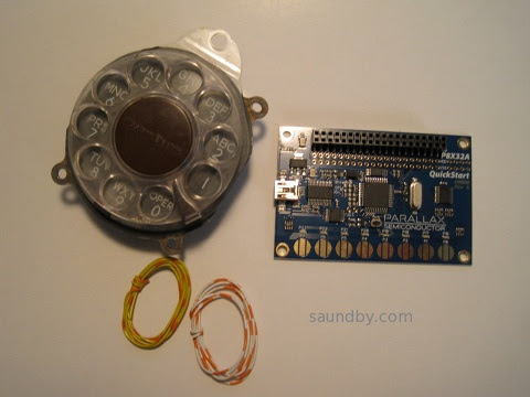
P8X32A Propeller Quickstart Board...Telephone Rotary Dial....Hmmmmmmmm.
Tuesday, July 10, 2012
Gadget Gangster QuickVGA+ for Parallax Propellor

Propeller Quickstart Add-Ons Galore
I mentioned that I picked up a Parallax Propeller Quickstart Board a while ago, and finally got around to playing with it.
Well, I've played with it a lot more now, in part thanks to a cool add-on board from an outfit called Gadget Gangster. I bought a Quickstart VGA+ board from them. It adds a nice VGA port (duh) as well a a PS/2 keyboard port (that's PS/2 as in the old IBM "Personal System/2", not Playstation 2), a stereo audio output, and a Wii Nunchuck port (or the classic controller can go here.) All on one little business card sized board, that fits right on top of the Parallax Quickstart board.
It's a nice combination of features. It's also got places for adding an SD card connector (which I've done), an IR port, and a composite video port.
There's a Pocket Mini Computer project built around this board, that's sort of a C-64 retro-clone kind of system. I look forward to trying that out some time when I get tired of playing with the Wii nunchuck as a raw sensor in software.
One note about that...
The nunchuck software that Gadget Gangster recommended didn't work right out of the box. I've posted na updated version of the nunchuck demo software at the Parallax Propeller Object Exchange, the place where Propeller users post their software for others to modify and use. I modified the demo to use the correct I/O lines for the QuickVGA+ board, and I added a bit of code to make it more clear what's going on with the accelerometers in the nunchuck.
Next, I'll be building up my Gadget Gangster QuickProto board, which came in a bundle deal with a QuickStart board (so, yes, I now have two Quickstart boards. And I ordered one for my daughter, too.
Pennies from Heaven
That's not all the Propellers running around the house, as it happens. While we were at the Parallax Robot Expo, my daughter and I picked up some stuff off the Free table. Among those items were a pair of slightly used Propeller Proto USB boards and one one-off PCB Propeller board that appears to mainly for servos. My daughter has one of the Proto boards and I have the other, as well as the one-off PCB.
I've already added PS/2 mouse and keyboard ports to my Prop Proto board, as well as a composite audio/video adapter. I have plans for this board...
I also found an early rev of the Parallax QuickStart Proto board in my bag of goodies, which I'm planning to use to put a sort of Elf II I/O interface on a Quickstart board. A hex keyboard, a pair of hex displays, some control switches, and hey-ho it's 1977 all over again. :)
Bottom line on the Propeller: It's heaps of fun to play with. Quick and easy. I keep thinking I ought to stop and read the documentation, but it hasn't been necessary, yet.
Monday, June 4, 2012
Parallax Propellor Quickstart Board
When I was at the Parallax Robotics Expo back in April, I picked up a P8X32A Quickstart Board. I've had my eye on the Propeller chip for a long time, I first heard of it before release. But to date, time spent on other things kept me from getting started with it.

The Time Window Opens
Finally, last Friday afternoon, I had a chunk of time open up as a result of being too ill to make a prior commitment. (I can't help but think of how many important things in my life have happened because of time made available through being too sick to do what I was supposed to do, or because I was stranded somewhere without transportation.) The tiny box for the Quickstart board had been living next to one of my computer keyboards for over a month, so I didn't even have to go looking for it. There was a USB cable of the correct type sitting in the drawer next to me. So I started in.
To keep it simple I decided to start out with the Parallax programming environment, Propeller Tool on my Windows 7 machine. I expect to try out Brad's Spin Tool, the other major development tool for Propeller, on my Mac and Linux machines a bit later.
I was pleased to see that it installed everything, the driver for the USB interface chip on the Quickstart board, the IDE, and the serial terminal tool for the Propellor. It says it does that before you download and install, but I was a bit unsure of whether the Terminal program would actually be in there before I actually installed the program.
Once the software was installed, I started it up then plugged in the Quickstart board. I got a ding-dong from Windows telling me it saw the hardware. I was able to find a menu item to report what chip version the software saw, and it saw my chip. I didn't get the message I expected from the documentation at first, a dialog pop-up. That appeared later, the first time I tried to send a program to the board.
About that...
Parallax has a tutorial that runs you through the initial steps of programming the Quickstart board. Aside from the fact that to get to each of the several pages you follow a link from the product page (the pages aren't linked together--that is, when you get to the bottom of one page there's no link to the next one) there's another oversight on these pages as well.
The page gives a short, simple program, describes what it does, then goes on to a slightly more sophisticated program. It tells you about how the editor behaves. But it doesn't tell you how to actually get the code on the chip.
Now, I'm not exactly a first timer here. I looked at the menu and saw "Run" at the top of the screen. But when I chose that I got a list of items, none of which were clearly "compile and run". So I started selecting things at random. I also didn't know whether to expect a simulation environment to start, or how to select between a simulator and the real hardware. I scanned the tutorial web page up to the third program in it, and found no specific instructions.
This is one of those things of which Sherlock Holmes remarked, "the answer is perfectly obvious, once you know it." There is no simulation environment in the free tool, that costs extra (I wish Parallax could follow Atmel's example in providing it with the free tool, the first job I applied an AVR to happened because I was able to use the simulation tool to verify the software timings I needed). And the Run=>Compile Current=>Load EEPROM or Run=>Compile Current=>Load RAM would either have done enough to let me get what I wanted--the sample code running on the target hardware.
But that wasn't clear. I was doing a quick try it and see, so I hadn't spent time with the chip's datasheet yet to learn about how it loads and runs software, what facilities it has for storage, what the implications are of loading EEPROM vs. loading RAM (I didn't even know if they were both program storage, for all I knew one was program storage and the other was for loading an initial state for testing.)
So I was a bit stymied until I just decided to try things at random and see what happened.
At the bottom of the tutorial page is a short table describing the shortcut keys and what they do. Below the actual step-by-step examples that omit instructions for how to compile and run the code. There they describe F10 and F11, for example, and the implications of each choice (RAM or EEPROM).
I managed to get the short initial program (which lights an LED) loaded and running. The LED lit up. There was much rejoicing.
Demo, Demo, Who's Got the Demo?
The next thing I started to wonder about was the demo that showed off the touchpads by lighting up the LEDs when the pads are touched. This hadn't appeared to be pre-loaded like demos often are on other processors. Nor did there appear to be anything obvious among the Propeller code that came with the IDE (another thing I fouond by spelunking, rather than as a result of documentation.) There were no projects with names like "Quickstart Board Demo" or "Touchpad Demo" or whatever. Nearly all the demos appeared to be for hardware I didn't have.
At first I went back to the Quickstart tutorials on the web. I did searches for the demo on the Parallax website and through Google, but the closest I came up with was modified versions of the demo listed in a forum thread. I did find the demo later, but it was only by going back and looking for it time after time that I finally located it today, my fourth day trying, here, on the Parallax Semiconductor Quickstart product page, not on the Propeller downloads page or the Parallax store product page, where there are lots of other downloads but not this one. The location is so subtle, that even after I found it earlier today it just took me five minutes of backtracking to find the right page over again. It's on the linked page, at the end of the list of downloads at the bottom. Direct Link to P8X32A Quickstart LED-Touchpad Demo Software Download
Well, back to last Friday. The demo was interesting to me, but while I was looking for it I came across information about the video capabilities of the Propeller. Frankly, while I'd heard the Propeller did video I just figured it was something along the lines of bit-bashed video like what I've done with several other microcontrollers. I've even generated video from a little Atmel AVR ATTiny12 with nothing more than a software loop and a resistor divider-no fancy shift registers or anything.
Needless to say, it was pretty simple video. No colorburst, no color. But it got some data out of the chip on a two-pin interface nicely (three levels are needed for even black and white video to get the sync signals for timing in addition to the black and white pixel data.)
The Propeller goes way, way beyond this. It's got both NTSC and VGA signal generation hardware on board. And it's not just single bit video, either. It can generate full color at a number of resolutions. This I had to try. But my little Quickstart board doesn't have a video output on it. I looked at the Propeller Demo Board and saw that it had a video interface. It was just a 3-resistor DAC and an RCA jack, so I decided to make one.

At first, the video was pretty wonky. Then I realized I had the resistor that's supposed to go to P13 going to P15. Once I fixed that, it was better, but still not good. The graphics demo ran OK, but one of the text demos wouldn't even sync properly, the other had poor contrast. The thought crossed my mind that either the timing in the Propeller wasn't much better than my old Atari Pong or that the provided 5MHz crystal meant that the timing wasn't right on. But I've learned the hard way, time and time again, to suspect user error first.
I took another look at my too-quick and too-dirty video interface and found that the resistors that were supposed to go between P12 and P13 were swapped. A moment later I had pulled the pins from the plastic IDC header and moved them to the correct positions. This is why doing electronics when you're under the weather is not always a good idea. Fortunately this wasn't a mistake that'd let the smoke out.
Once that was done, the video looked great on all the demos. I then had to make a batter adapter so that I could try it out on the big screen TV in my living room. A quad-AA battery pack came to hand quickly enough, one of the ones with the 9V snap connector on the end. Then I soldered a 9V snap connector pigtail to another IDC header and spliced in an IDC socket pigtail. That way I'd still have a place to put my ground pin from the Q&D video interface without soldering it to the battery connector. As a final refinement, I put a slider switch in line on the positive battery wire to act as a power switch.
Once that and the video adapter were plugged into the Quickstart board, I took it out to the living room and hooked up to a free composite video input. It looked great.
I spent the rest of my time mucking around with the code of the various NTSC video demos. Spin is a really easy language to learn, if you've got any programming experience it'll come easily. It's even simple enough I could easily see teaching it as a first language to new programmers (with a Propellor board on hand, of course, to get the full hardware + software experience!)
Cleaning Up Shop
As mentioned, I have now been playing with my new board for four days. In spite of a couple of minor snags (figuring out what to choose to compile and run my programs, finding the demo for the Quickstart board itself) it's been a very rewarding use of my time. I can see now why people who've been raving about this controller for five or six years are excited about it.
After my first night playing with the board, I learned while reading the Parallax forums that the Propeller could also do RF-modulated video. That's what I spent mid-day Saturday playing with. I put rabbit ears on my big screen (talk about incongruity!) and a pair of jumpers on the RCA jack and managed to receive video from the Propeller from about 25 feet away. What worked even better was an LCD handheld television left over from the analog TV transmission days. I was able to get as far as 10 feet from my back door, a total distance of about 50 feet, and still get good reception. I don't think it's making it as far as the neighbor's house, though (fortunately.)
Yesterday I buckled down to some more structured learning of the Spin language, reading the Propeller Manual and Datasheet, and so on. Today I'm continuing that, working my way through tutorials and such. I also took a look in the goodie bag I filled at the Free tables at the Robotics Expo--there are a couple of Propeller boards in there that I can't wait to find a use for now.
Tweet
The P8X32A Quickstart Board, in the obligatory Altoids tin for scale.
The Time Window Opens
Finally, last Friday afternoon, I had a chunk of time open up as a result of being too ill to make a prior commitment. (I can't help but think of how many important things in my life have happened because of time made available through being too sick to do what I was supposed to do, or because I was stranded somewhere without transportation.) The tiny box for the Quickstart board had been living next to one of my computer keyboards for over a month, so I didn't even have to go looking for it. There was a USB cable of the correct type sitting in the drawer next to me. So I started in.
To keep it simple I decided to start out with the Parallax programming environment, Propeller Tool on my Windows 7 machine. I expect to try out Brad's Spin Tool, the other major development tool for Propeller, on my Mac and Linux machines a bit later.
I was pleased to see that it installed everything, the driver for the USB interface chip on the Quickstart board, the IDE, and the serial terminal tool for the Propellor. It says it does that before you download and install, but I was a bit unsure of whether the Terminal program would actually be in there before I actually installed the program.
Once the software was installed, I started it up then plugged in the Quickstart board. I got a ding-dong from Windows telling me it saw the hardware. I was able to find a menu item to report what chip version the software saw, and it saw my chip. I didn't get the message I expected from the documentation at first, a dialog pop-up. That appeared later, the first time I tried to send a program to the board.
About that...
Parallax has a tutorial that runs you through the initial steps of programming the Quickstart board. Aside from the fact that to get to each of the several pages you follow a link from the product page (the pages aren't linked together--that is, when you get to the bottom of one page there's no link to the next one) there's another oversight on these pages as well.
The page gives a short, simple program, describes what it does, then goes on to a slightly more sophisticated program. It tells you about how the editor behaves. But it doesn't tell you how to actually get the code on the chip.
Now, I'm not exactly a first timer here. I looked at the menu and saw "Run" at the top of the screen. But when I chose that I got a list of items, none of which were clearly "compile and run". So I started selecting things at random. I also didn't know whether to expect a simulation environment to start, or how to select between a simulator and the real hardware. I scanned the tutorial web page up to the third program in it, and found no specific instructions.
This is one of those things of which Sherlock Holmes remarked, "the answer is perfectly obvious, once you know it." There is no simulation environment in the free tool, that costs extra (I wish Parallax could follow Atmel's example in providing it with the free tool, the first job I applied an AVR to happened because I was able to use the simulation tool to verify the software timings I needed). And the Run=>Compile Current=>Load EEPROM or Run=>Compile Current=>Load RAM would either have done enough to let me get what I wanted--the sample code running on the target hardware.
But that wasn't clear. I was doing a quick try it and see, so I hadn't spent time with the chip's datasheet yet to learn about how it loads and runs software, what facilities it has for storage, what the implications are of loading EEPROM vs. loading RAM (I didn't even know if they were both program storage, for all I knew one was program storage and the other was for loading an initial state for testing.)
So I was a bit stymied until I just decided to try things at random and see what happened.
At the bottom of the tutorial page is a short table describing the shortcut keys and what they do. Below the actual step-by-step examples that omit instructions for how to compile and run the code. There they describe F10 and F11, for example, and the implications of each choice (RAM or EEPROM).
I managed to get the short initial program (which lights an LED) loaded and running. The LED lit up. There was much rejoicing.
Demo, Demo, Who's Got the Demo?
The next thing I started to wonder about was the demo that showed off the touchpads by lighting up the LEDs when the pads are touched. This hadn't appeared to be pre-loaded like demos often are on other processors. Nor did there appear to be anything obvious among the Propeller code that came with the IDE (another thing I fouond by spelunking, rather than as a result of documentation.) There were no projects with names like "Quickstart Board Demo" or "Touchpad Demo" or whatever. Nearly all the demos appeared to be for hardware I didn't have.
At first I went back to the Quickstart tutorials on the web. I did searches for the demo on the Parallax website and through Google, but the closest I came up with was modified versions of the demo listed in a forum thread. I did find the demo later, but it was only by going back and looking for it time after time that I finally located it today, my fourth day trying, here, on the Parallax Semiconductor Quickstart product page, not on the Propeller downloads page or the Parallax store product page, where there are lots of other downloads but not this one. The location is so subtle, that even after I found it earlier today it just took me five minutes of backtracking to find the right page over again. It's on the linked page, at the end of the list of downloads at the bottom. Direct Link to P8X32A Quickstart LED-Touchpad Demo Software Download
Well, back to last Friday. The demo was interesting to me, but while I was looking for it I came across information about the video capabilities of the Propeller. Frankly, while I'd heard the Propeller did video I just figured it was something along the lines of bit-bashed video like what I've done with several other microcontrollers. I've even generated video from a little Atmel AVR ATTiny12 with nothing more than a software loop and a resistor divider-no fancy shift registers or anything.
Needless to say, it was pretty simple video. No colorburst, no color. But it got some data out of the chip on a two-pin interface nicely (three levels are needed for even black and white video to get the sync signals for timing in addition to the black and white pixel data.)
The Propeller goes way, way beyond this. It's got both NTSC and VGA signal generation hardware on board. And it's not just single bit video, either. It can generate full color at a number of resolutions. This I had to try. But my little Quickstart board doesn't have a video output on it. I looked at the Propeller Demo Board and saw that it had a video interface. It was just a 3-resistor DAC and an RCA jack, so I decided to make one.
It doesn't get much quicker and dirtier. It took longer to pull the parts than to assemble.
At first, the video was pretty wonky. Then I realized I had the resistor that's supposed to go to P13 going to P15. Once I fixed that, it was better, but still not good. The graphics demo ran OK, but one of the text demos wouldn't even sync properly, the other had poor contrast. The thought crossed my mind that either the timing in the Propeller wasn't much better than my old Atari Pong or that the provided 5MHz crystal meant that the timing wasn't right on. But I've learned the hard way, time and time again, to suspect user error first.
I took another look at my too-quick and too-dirty video interface and found that the resistors that were supposed to go between P12 and P13 were swapped. A moment later I had pulled the pins from the plastic IDC header and moved them to the correct positions. This is why doing electronics when you're under the weather is not always a good idea. Fortunately this wasn't a mistake that'd let the smoke out.
Once that was done, the video looked great on all the demos. I then had to make a batter adapter so that I could try it out on the big screen TV in my living room. A quad-AA battery pack came to hand quickly enough, one of the ones with the 9V snap connector on the end. Then I soldered a 9V snap connector pigtail to another IDC header and spliced in an IDC socket pigtail. That way I'd still have a place to put my ground pin from the Q&D video interface without soldering it to the battery connector. As a final refinement, I put a slider switch in line on the positive battery wire to act as a power switch.
Once that and the video adapter were plugged into the Quickstart board, I took it out to the living room and hooked up to a free composite video input. It looked great.
I spent the rest of my time mucking around with the code of the various NTSC video demos. Spin is a really easy language to learn, if you've got any programming experience it'll come easily. It's even simple enough I could easily see teaching it as a first language to new programmers (with a Propellor board on hand, of course, to get the full hardware + software experience!)
Cleaning Up Shop
As mentioned, I have now been playing with my new board for four days. In spite of a couple of minor snags (figuring out what to choose to compile and run my programs, finding the demo for the Quickstart board itself) it's been a very rewarding use of my time. I can see now why people who've been raving about this controller for five or six years are excited about it.
After my first night playing with the board, I learned while reading the Parallax forums that the Propeller could also do RF-modulated video. That's what I spent mid-day Saturday playing with. I put rabbit ears on my big screen (talk about incongruity!) and a pair of jumpers on the RCA jack and managed to receive video from the Propeller from about 25 feet away. What worked even better was an LCD handheld television left over from the analog TV transmission days. I was able to get as far as 10 feet from my back door, a total distance of about 50 feet, and still get good reception. I don't think it's making it as far as the neighbor's house, though (fortunately.)
Yesterday I buckled down to some more structured learning of the Spin language, reading the Propeller Manual and Datasheet, and so on. Today I'm continuing that, working my way through tutorials and such. I also took a look in the goodie bag I filled at the Free tables at the Robotics Expo--there are a couple of Propeller boards in there that I can't wait to find a use for now.
Saturday, April 14, 2012
Parallax Robot Expo
My daughter and I went to the Parallax Robot Expo today and had a great time. It's neat having an event like this only about 45 minutes from home. My daughter has a couple of BOE-Bot robots and a bunch of additional bits she enjoys working with. I'm into anything microprocessor or microcontroller, and I think Parallax is a neat company that makes great products.
We were a bit worried about the effects of the weather. We left home with snow falling and drove through a rainstorm on the way. When we got there it was only raining lightly. Even if it had been raining, everything was either under tents or inside. It wouldn't have been necessary to do more than duck across a few feet of open sky in any case.
As it happened, things only got better as the day went on.
We had a really good time checking out the various demos. They had one tent with activities, laptops set up with boards hooked up to them, where people could get their feet wet in programming the boards to blink lights, run servos, sound off on piezos, etc. We didn't check that out too closely since we can do that at home.
Alongside it was a "Learn to Solder" area with several tables. You get to build an S-2 Robot LED badge. Not an actual S-2 robot, mind you, but a little hang around your neck badge shaped like the Scribbler 2. It's got a 7 color LED on it, a switch, a battery, and some embedded logic. It's a neat little thing and it's entirely free.
I made one though I'm no newcomer to soldering. I had a very helpful young man making sure I prepped the parts properly and oriented them correctly. He was also able to answer my question about whether there was logic embedded in the printed circuit board.
The factory tour was also very nice. They've got some automation they're justifiably proud of. I'm surprised that it appears they actually use a CNC to make production parts. I'd have expected higher volume processes for them.
Also inside was a display and presentation area. They had various talks through the day by very approachable people with experience directly relevant to the attendees. It was interesting hearing them talk about their technical work and their work to develop their businesses. We weren't able to hear all the talks we would have liked.
Back outside there was a tent for vendors--the show prices on Parallax products were amazingly great and there were some other great vendors there, too. There was a show area for other companies, Panavise was among the companies showing there (IMO, yes, their products are worth every dime!)
Maxi Swag
One of the coolest things there, a real unexpected treat, was the Free Stuff tables. There were all sorts of free parts and boards and what I assume was discontinued product. I got a book on programming the SX microcontroller, a Javelin Stamp, some sort of Propellor board, and some other fun electronic "Junque Box" goodies, as did my daughter (I think I'll be showing her how to wire up a CCFL this weekend, there were packs of them on the tables.)
We both had a great time. My daughter got really excited and couldn't wait to get back home to her electronics. We picked up some great project books for her, cheap.
If you get a chance to go on Saturday, I recommend it highly.
Tweet
We were a bit worried about the effects of the weather. We left home with snow falling and drove through a rainstorm on the way. When we got there it was only raining lightly. Even if it had been raining, everything was either under tents or inside. It wouldn't have been necessary to do more than duck across a few feet of open sky in any case.
As it happened, things only got better as the day went on.
We had a really good time checking out the various demos. They had one tent with activities, laptops set up with boards hooked up to them, where people could get their feet wet in programming the boards to blink lights, run servos, sound off on piezos, etc. We didn't check that out too closely since we can do that at home.
Alongside it was a "Learn to Solder" area with several tables. You get to build an S-2 Robot LED badge. Not an actual S-2 robot, mind you, but a little hang around your neck badge shaped like the Scribbler 2. It's got a 7 color LED on it, a switch, a battery, and some embedded logic. It's a neat little thing and it's entirely free.
I made one though I'm no newcomer to soldering. I had a very helpful young man making sure I prepped the parts properly and oriented them correctly. He was also able to answer my question about whether there was logic embedded in the printed circuit board.
The factory tour was also very nice. They've got some automation they're justifiably proud of. I'm surprised that it appears they actually use a CNC to make production parts. I'd have expected higher volume processes for them.
Also inside was a display and presentation area. They had various talks through the day by very approachable people with experience directly relevant to the attendees. It was interesting hearing them talk about their technical work and their work to develop their businesses. We weren't able to hear all the talks we would have liked.
Back outside there was a tent for vendors--the show prices on Parallax products were amazingly great and there were some other great vendors there, too. There was a show area for other companies, Panavise was among the companies showing there (IMO, yes, their products are worth every dime!)
Maxi Swag
One of the coolest things there, a real unexpected treat, was the Free Stuff tables. There were all sorts of free parts and boards and what I assume was discontinued product. I got a book on programming the SX microcontroller, a Javelin Stamp, some sort of Propellor board, and some other fun electronic "Junque Box" goodies, as did my daughter (I think I'll be showing her how to wire up a CCFL this weekend, there were packs of them on the tables.)
We both had a great time. My daughter got really excited and couldn't wait to get back home to her electronics. We picked up some great project books for her, cheap.
If you get a chance to go on Saturday, I recommend it highly.
Monday, January 16, 2012
8085 Resurgent: Back to the MAG-85
I took a look at my own website the other day and realized it's been far too long since I have updated certain items there. Most noticeable to me was my MAG-85 project, an 8085-based micro trainer. There are a bunch of things I thought I'd posted over a year ago, but the information isn't there.
Obviously I never did it. Sorry about that.
The front page image for the 8085 project is was a really ugly thing I took at a very interim stage while I was doing regular updates on the project. If I wanted to scare someone off the project, I think that picture is what I'd use. What a rat's nest!

Shortly after that picture was taken I built a real front panel and enclosure. It's been happily living in that enclosure for well over a year, but I never posted the info on it. In fact, I've just started taking it apart in preparation for making some improvements. Since I like to take pictures of my work for documentation purposes (like getting the right connectors back in the right places), I took some photos of the partially-disassembled unit as it is before I make the updates. Here's one:

Here you can see that it's not so ugly as before. The LED to the left of the LCD display is controlled by the 8085's SOD output. The eight LEDs below the display are controlled by the 8085's OUT 01 command and held in their state by a register. The eight switches below that are on the 8085's IN 01 port.
The program that's running currently reads the position of the switches and outputs a byte to the LED bank to match what it sees on the input. It also reads the keyboard and sends the ASCII + 0x30 character to the screen that it reads from the keyboard (which is in IN 00). The LCD display is on the OUT 00 port.
The four push buttons above the keyboard are, from left (red) to right:
RESET
TRAP
RST7.5
RST5.5
In the crude OS/monitor I have running on the MAG-85 now, TRAP acts as an "Escape" key that returns control to the OS. This allows miscreant programs to be stopped and memory examined any time, since TRAP isn't maskable.
RST7.5 is used as the user vector to the start of the application program in memory. In essence, this is the "GO" or "Execute" button.
RST5.5 is also a user vector that should point to a subroutine that does something and returns. Either the application program should initialize it, or it has to be initialized by hand in the monitor.
The keyboard itself uses RST6.5 to read a key value into a buffer, where an OS routine can pick it up/translate it, etc. The keycap legends allow for several uses of the keys. The typical use of the yellow keys is hexadecimal number entry. But they can also be used as arrow keys and fire button (9) for games.
The top row has the IN or Enter key in red, the backspace (BK) in blue, the (M) mode and edit/view (e/v) keys in gray. The edit/view key toggles a flag in the OS that switches between a memory protecting mode (view) and editing mode in the various modes. The mode key modifies the mode variable in the system to switch between Memory, Register, and I/O port viewing or editing. It's possible to change from editing to viewing and back again while in any of the modes.
Current Rework
My current plans for reworking the MAG-85 have to do with replacing the buttons used for RESET, TRAP and the RSTs, plus improving the ergonomics of the unit a bit by replacing the top and bottom panels, which were hand-made on hardboard, with some nicer CNC'd panels that reposition some of the controls (I switched off the unit more than once when I meant to switch on or off the backlight for the LCD.)
The four pushbuttons above the keyboard are some really awful buttons. They ring like bells, causing all sorts of debounce problems. I have both hardware and software debouncing on them right now, and it *mostly* works. I think part of why I stopped posting before was that I wanted to kill this problem before I posted, so as to avoid causing anyone else the headaches I've had with these switches. And, as you can see, those switches are still in there.
A sideline on the current work is also preparing for a couple of improvements that have been planned since the beginning, but haven't happened yet. One is to put a nice little door in so that the NOVRAM/EEPROM/EPROM memory can be swapped out without opening the whole unit. Right now I unscrew the end pieces then pop out the face panel to get at the memory socket. Which is not clean, quick, or easy. I have to get the cables all to go back to their places each time I put it back together. A couple of times I've pulled out one of the input cables by accident, then wondered why the keyboard or switches aren't talking when I get it back together.
The other is preparing to mount a battery pack inside, so that I can go cordless with this thing. A lot of what I've been doing in design tweaks is reducing the power used by the system. Finding a good brightness for the backlight, putting a switch on the backlight so that I can turn it off when I'm in good light, reducing the brightness of the power LED and the I/O LEDs, that sort of thing. As well as looking at my nascent OS to see if there are things I can do there that will reduce power while staying out of the way of the user's programs.
I'm also planning on adding another memory socket for an EPROM. It won't have a ZIF socket in it like the one that's there now, but I'm getting to the point of wanting a more permanent memory for the OS, with the NOVRAM left for user space programs. This may involve some rejiggering of the memory map, since for mechanical reasons I'd like to have the removable memory in the center of the PCB side to side.
I'm also looking at adding an expansion port or two on the new end plates, which begs the question of whether to use a standard connector with a more or less standard wiring for the port (like a PC's bidirectional parallel port) or whether to roll my own for the sake of less constraint on how the lines are used. Basically just bringing the lines from the I/O buffer registers straight out of the box along with power and ground. This is my preference for a number of reasons, but there's an appeal to letting the MAG-85 drive standard I/O devices, too.
The addition of a serial port, either at TTL levels or a standard RS-232C port is another possibility I keep playing with. I've kept SID available for this possibility, though I was tempted to use it as either a user digital I/O or a memory bankswitch I/O or something of the sort. Being able to connect the MAG-85 straight to a terminal would be really nice, so I'm leaning toward an RS-232C port.
But if I do that, I'll need a separate set of I/O routines for that port that allow it to be the primary user I/O for the OS. So if I do that, it'll probably be deferred until some other things happen first.
Like finishing the OS well enough to post it.
Finishing the MAG-85 Operating System
I haven't posted the OS yet because it's still in a fairly yucky developmental state. That and my test hardware still has the crummy switches that do nasty things to me at times, and there's lots of code in the OS just to try to deal with them that can probably come out once I've got decent switches in.
So my present software objective is to clean up the OS and put a bow on it so that I can "ship" it to a download on my site. I may end up cutting some of the features, but there's also the possibility that I'll end up cleaning them up because I've already got too much other code running around that uses them. The core basics are the ability to view and edit the system's memory, and execute a program starting at some given address. I'll guarantee that much.
I think the ability to view and edit register values is pretty well sewn, too. It's possible to bork the OS by doing something stupid here, but I'm not trying to protect the user from being stupid. Press TRAP (probably to be labelled ESC) and the OS will restart and reset any values it needs to function (I hope!)
The ability to view inputs and edit outputs interactively shouldn't be a problem, either, but it's not an immediate priority. If it happens effortlessly, it'll be in the initial release. Otherwise, I won't hold up the release for it.
I've also got another mode that is enabled in some versions for viewing/setting user variables in the OS, such as the RST5.5 and RST7.5 vectors, selecting different display formats, setting the size of the LCD, and so on. I can pretty well guarantee that the full-up version of this will not be in the initial release, though a cut-rate version of it may be. That would mean that you would set these variables yourself when putting the code on your own MAG-85.
If I do go to a design that uses two memories, one rewritable in system and the other not, I'll have to put these variables in RAM, or expect that they be set once and for all in the firmware. I'd like to be able to provide an EPROM at some point for people who want to build a MAG-85 and get up and running without having to put the OS in themselves. But if I do, I either need to put some system information in the NOVRAM memory space (like the height/width of the LCD display) or require that only one size of LCD be used with a specific version of the OS. Since I'm looking forward to building another MAG-85 with a larger display (perhaps 32 characters wide by 4 lines high), I'd like to keep the OS flexible. The initial display routines will only use a portion of displays larger than 20x2, but the user programs can use the larger displays and the OS can be updated later to have multiple display formats that the user can select.
But right now, I just need to drive a stake through its heart and get a workable version out the door. :)
Tweet
Obviously I never did it. Sorry about that.
The front page image for the 8085 project
A Very Ugly Looking 8085 Computer
Shortly after that picture was taken I built a real front panel and enclosure. It's been happily living in that enclosure for well over a year, but I never posted the info on it. In fact, I've just started taking it apart in preparation for making some improvements. Since I like to take pictures of my work for documentation purposes (like getting the right connectors back in the right places), I took some photos of the partially-disassembled unit as it is before I make the updates. Here's one:
A bit ugly with the top and bottom panels off, connectors and wires trailing out, but not so bad at the first photo.
Here you can see that it's not so ugly as before. The LED to the left of the LCD display is controlled by the 8085's SOD output. The eight LEDs below the display are controlled by the 8085's OUT 01 command and held in their state by a register. The eight switches below that are on the 8085's IN 01 port.
The program that's running currently reads the position of the switches and outputs a byte to the LED bank to match what it sees on the input. It also reads the keyboard and sends the ASCII + 0x30 character to the screen that it reads from the keyboard (which is in IN 00). The LCD display is on the OUT 00 port.
The four push buttons above the keyboard are, from left (red) to right:
RESET
TRAP
RST7.5
RST5.5
In the crude OS/monitor I have running on the MAG-85 now, TRAP acts as an "Escape" key that returns control to the OS. This allows miscreant programs to be stopped and memory examined any time, since TRAP isn't maskable.
RST7.5 is used as the user vector to the start of the application program in memory. In essence, this is the "GO" or "Execute" button.
RST5.5 is also a user vector that should point to a subroutine that does something and returns. Either the application program should initialize it, or it has to be initialized by hand in the monitor.
The keyboard itself uses RST6.5 to read a key value into a buffer, where an OS routine can pick it up/translate it, etc. The keycap legends allow for several uses of the keys. The typical use of the yellow keys is hexadecimal number entry. But they can also be used as arrow keys and fire button (9) for games.
The top row has the IN or Enter key in red, the backspace (BK) in blue, the (M) mode and edit/view (e/v) keys in gray. The edit/view key toggles a flag in the OS that switches between a memory protecting mode (view) and editing mode in the various modes. The mode key modifies the mode variable in the system to switch between Memory, Register, and I/O port viewing or editing. It's possible to change from editing to viewing and back again while in any of the modes.
Current Rework
My current plans for reworking the MAG-85 have to do with replacing the buttons used for RESET, TRAP and the RSTs, plus improving the ergonomics of the unit a bit by replacing the top and bottom panels, which were hand-made on hardboard, with some nicer CNC'd panels that reposition some of the controls (I switched off the unit more than once when I meant to switch on or off the backlight for the LCD.)
The four pushbuttons above the keyboard are some really awful buttons. They ring like bells, causing all sorts of debounce problems. I have both hardware and software debouncing on them right now, and it *mostly* works. I think part of why I stopped posting before was that I wanted to kill this problem before I posted, so as to avoid causing anyone else the headaches I've had with these switches. And, as you can see, those switches are still in there.
A sideline on the current work is also preparing for a couple of improvements that have been planned since the beginning, but haven't happened yet. One is to put a nice little door in so that the NOVRAM/EEPROM/EPROM memory can be swapped out without opening the whole unit. Right now I unscrew the end pieces then pop out the face panel to get at the memory socket. Which is not clean, quick, or easy. I have to get the cables all to go back to their places each time I put it back together. A couple of times I've pulled out one of the input cables by accident, then wondered why the keyboard or switches aren't talking when I get it back together.
The other is preparing to mount a battery pack inside, so that I can go cordless with this thing. A lot of what I've been doing in design tweaks is reducing the power used by the system. Finding a good brightness for the backlight, putting a switch on the backlight so that I can turn it off when I'm in good light, reducing the brightness of the power LED and the I/O LEDs, that sort of thing. As well as looking at my nascent OS to see if there are things I can do there that will reduce power while staying out of the way of the user's programs.
I'm also planning on adding another memory socket for an EPROM. It won't have a ZIF socket in it like the one that's there now, but I'm getting to the point of wanting a more permanent memory for the OS, with the NOVRAM left for user space programs. This may involve some rejiggering of the memory map, since for mechanical reasons I'd like to have the removable memory in the center of the PCB side to side.
I'm also looking at adding an expansion port or two on the new end plates, which begs the question of whether to use a standard connector with a more or less standard wiring for the port (like a PC's bidirectional parallel port) or whether to roll my own for the sake of less constraint on how the lines are used. Basically just bringing the lines from the I/O buffer registers straight out of the box along with power and ground. This is my preference for a number of reasons, but there's an appeal to letting the MAG-85 drive standard I/O devices, too.
The addition of a serial port, either at TTL levels or a standard RS-232C port is another possibility I keep playing with. I've kept SID available for this possibility, though I was tempted to use it as either a user digital I/O or a memory bankswitch I/O or something of the sort. Being able to connect the MAG-85 straight to a terminal would be really nice, so I'm leaning toward an RS-232C port.
But if I do that, I'll need a separate set of I/O routines for that port that allow it to be the primary user I/O for the OS. So if I do that, it'll probably be deferred until some other things happen first.
Like finishing the OS well enough to post it.
Finishing the MAG-85 Operating System
I haven't posted the OS yet because it's still in a fairly yucky developmental state. That and my test hardware still has the crummy switches that do nasty things to me at times, and there's lots of code in the OS just to try to deal with them that can probably come out once I've got decent switches in.
So my present software objective is to clean up the OS and put a bow on it so that I can "ship" it to a download on my site. I may end up cutting some of the features, but there's also the possibility that I'll end up cleaning them up because I've already got too much other code running around that uses them. The core basics are the ability to view and edit the system's memory, and execute a program starting at some given address. I'll guarantee that much.
I think the ability to view and edit register values is pretty well sewn, too. It's possible to bork the OS by doing something stupid here, but I'm not trying to protect the user from being stupid. Press TRAP (probably to be labelled ESC) and the OS will restart and reset any values it needs to function (I hope!)
The ability to view inputs and edit outputs interactively shouldn't be a problem, either, but it's not an immediate priority. If it happens effortlessly, it'll be in the initial release. Otherwise, I won't hold up the release for it.
I've also got another mode that is enabled in some versions for viewing/setting user variables in the OS, such as the RST5.5 and RST7.5 vectors, selecting different display formats, setting the size of the LCD, and so on. I can pretty well guarantee that the full-up version of this will not be in the initial release, though a cut-rate version of it may be. That would mean that you would set these variables yourself when putting the code on your own MAG-85.
If I do go to a design that uses two memories, one rewritable in system and the other not, I'll have to put these variables in RAM, or expect that they be set once and for all in the firmware. I'd like to be able to provide an EPROM at some point for people who want to build a MAG-85 and get up and running without having to put the OS in themselves. But if I do, I either need to put some system information in the NOVRAM memory space (like the height/width of the LCD display) or require that only one size of LCD be used with a specific version of the OS. Since I'm looking forward to building another MAG-85 with a larger display (perhaps 32 characters wide by 4 lines high), I'd like to keep the OS flexible. The initial display routines will only use a portion of displays larger than 20x2, but the user programs can use the larger displays and the OS can be updated later to have multiple display formats that the user can select.
But right now, I just need to drive a stake through its heart and get a workable version out the door. :)
Thursday, January 5, 2012
New Call Sign, New QSL Card
I'm afraid I didn't care much for the Extra class call sign I got from the sequential call sign assignment. It was AG6HU. Before it was assigned, I saw on AE7Q's site that I was likely to get a call from the range AG6HT through AG6HV. I would have been OK with HT or HV, but I was hoping I wouldn't get HU. The call sign is funky enough with the AG prefix, but with an HU suffix there's just nothing there to love.
I tried, I really did. I tried coming up with interesting phoney phonetics for it ("higher up", "hugely unpopular", "hic up", etc.) What really sealed that call's fate for me was when I tried telling it to people. It took a minimum of three tried to get it across, even when using the International Phonetic Alphabet. That's bad.
So I applied for a vanity call sign. I didn't rush right out, though I didn't dilly-dally, either. Knowing that I wasn't going to stick with AG6HU meant that I wanted to get a new call before establishing much of an identity with that call. I spent a lot of time thinking about what I'd want that'd still be fun to have 20 plus years from now.
Since retrocomputing and microcontrollers are both hobbies of mine, the call W8BIT seemed appropriate. That's what I put at the top of the list, and that's what I got. W6CPU and W6TTY were high on my list. I didn't realize it when I applied, but another ham applied for W6TTY a few days before I did, and got that assigned during the 18 day waiting period for my new call (not that it mattered, since my first choice was available, but an example of a good reason to have more than one choice and be prepared to not get your first choice.)
Another one that would have been a lot of fun is KO5MAC, since I'm a fan of the COSMAC microprocessor (the RCA 1802.) It's a bit more specialized than simply "8BIT", so it ended up as a lower preference. Beyond the first three choices I listed, I didn't worry much about the order of the other calls I put on the list relative to my preferences. Any of them were better than AG6HU, and I pretty well expected that things weren't very likely at all to go past the top three. KO5MAC would probably have been my fourth choice if I had arranged them. It's an awfully fun call sign, just like the 1802 is a really fun chip.
I considered having a call with my current favorite microcontroller referenced, the Atmel AVR, like, say K6AVR or W6AVR (no idea if these are in use or not.) But that seemed potentially even a bit more narrow than the COSMAC reference, especially when viewed from the perspective of 20 years from now.
I got my new call sign on the 4th, I'd already figured out what I wanted to do for my QSL card. I got 100 of them printed up today. Here's what it looks like:

Ready to Go, Almost
On the more practical side of amateur radio--making actual radio contacts--I'm still moving things forward. Yesterday afternoon I replaced the towels stuffed in the window where the antenna cable comes through with a purpose-made wooden feedthrough. It looks a lot less "redneck" than the towels stuffed in a window casement.
Unfortunately, I don't have a good ground to the transceiver in its temporary home yet. I'd hoped to have time to pull that in yesterday but time ran short. But that's next. I'm not too worried about the ground when I'm just listening in, but before I key the mike I want to have a good ground on the radio's chassis. Then I'll be ready to jump into 40 meters, and possibly 15 meters.
I've been listening in a lot on 40 meters over the past week, and I'm starting to get a pretty good feel for the band. Like what frequencies folks are using pretty commonly, what sort of traffic is going on when (daily nets, some of the weekly nets, and so on.) So I'm pretty confident I won't seem to be a complete and total lid when I do key up. Though I'm prepared to make _some_ mistakes, it's part of the learning process.
Then the next major step is to clear out my corner of the garage, put in an AC/heater unit in the wall, a raised floor, and a bit of insulation. A few more touches like a mecca ground plate and feedthrough panel then I'm ready to put in shelves and furniture.
Somewhere in there I want to get or build a decent morse key or keyer. All I have on hand right now are a couple of ones of about the quality that were in kid's science kits 30-40 years ago.
So long as my current antenna keeps me going, I'll just go with it until the new radio shack is done before hanging up a new multiband antenna. A G5RV has been highly recommended to me by at least two hams. I've got a good idea of where a full size one would go on my property, and I'm looking to see if I can fit in a double-size one at right angles, more or less, to the first. That'd (hopefully) get me on the 160m band, too.
Lots to do, lots to do. In the meanwhile I'm going to grab my HT and make some contacts on 2m simplex.
73
Tweet
I tried, I really did. I tried coming up with interesting phoney phonetics for it ("higher up", "hugely unpopular", "hic up", etc.) What really sealed that call's fate for me was when I tried telling it to people. It took a minimum of three tried to get it across, even when using the International Phonetic Alphabet. That's bad.
So I applied for a vanity call sign. I didn't rush right out, though I didn't dilly-dally, either. Knowing that I wasn't going to stick with AG6HU meant that I wanted to get a new call before establishing much of an identity with that call. I spent a lot of time thinking about what I'd want that'd still be fun to have 20 plus years from now.
Since retrocomputing and microcontrollers are both hobbies of mine, the call W8BIT seemed appropriate. That's what I put at the top of the list, and that's what I got. W6CPU and W6TTY were high on my list. I didn't realize it when I applied, but another ham applied for W6TTY a few days before I did, and got that assigned during the 18 day waiting period for my new call (not that it mattered, since my first choice was available, but an example of a good reason to have more than one choice and be prepared to not get your first choice.)
Another one that would have been a lot of fun is KO5MAC, since I'm a fan of the COSMAC microprocessor (the RCA 1802.) It's a bit more specialized than simply "8BIT", so it ended up as a lower preference. Beyond the first three choices I listed, I didn't worry much about the order of the other calls I put on the list relative to my preferences. Any of them were better than AG6HU, and I pretty well expected that things weren't very likely at all to go past the top three. KO5MAC would probably have been my fourth choice if I had arranged them. It's an awfully fun call sign, just like the 1802 is a really fun chip.
I considered having a call with my current favorite microcontroller referenced, the Atmel AVR, like, say K6AVR or W6AVR (no idea if these are in use or not.) But that seemed potentially even a bit more narrow than the COSMAC reference, especially when viewed from the perspective of 20 years from now.
I got my new call sign on the 4th, I'd already figured out what I wanted to do for my QSL card. I got 100 of them printed up today. Here's what it looks like:
Ready to Go, Almost
On the more practical side of amateur radio--making actual radio contacts--I'm still moving things forward. Yesterday afternoon I replaced the towels stuffed in the window where the antenna cable comes through with a purpose-made wooden feedthrough. It looks a lot less "redneck" than the towels stuffed in a window casement.
Unfortunately, I don't have a good ground to the transceiver in its temporary home yet. I'd hoped to have time to pull that in yesterday but time ran short. But that's next. I'm not too worried about the ground when I'm just listening in, but before I key the mike I want to have a good ground on the radio's chassis. Then I'll be ready to jump into 40 meters, and possibly 15 meters.
I've been listening in a lot on 40 meters over the past week, and I'm starting to get a pretty good feel for the band. Like what frequencies folks are using pretty commonly, what sort of traffic is going on when (daily nets, some of the weekly nets, and so on.) So I'm pretty confident I won't seem to be a complete and total lid when I do key up. Though I'm prepared to make _some_ mistakes, it's part of the learning process.
Then the next major step is to clear out my corner of the garage, put in an AC/heater unit in the wall, a raised floor, and a bit of insulation. A few more touches like a mecca ground plate and feedthrough panel then I'm ready to put in shelves and furniture.
Somewhere in there I want to get or build a decent morse key or keyer. All I have on hand right now are a couple of ones of about the quality that were in kid's science kits 30-40 years ago.
So long as my current antenna keeps me going, I'll just go with it until the new radio shack is done before hanging up a new multiband antenna. A G5RV has been highly recommended to me by at least two hams. I've got a good idea of where a full size one would go on my property, and I'm looking to see if I can fit in a double-size one at right angles, more or less, to the first. That'd (hopefully) get me on the 160m band, too.
Lots to do, lots to do. In the meanwhile I'm going to grab my HT and make some contacts on 2m simplex.
73
Tuesday, December 6, 2011
A Neat Modern Retro Computer: The New Elf II
My first computer was a version of the COSMAC Elf computer. It was a simple little computer, costing about $100 in 1976-77. The joy of it was that is was a real computer, and yet it was direct enough in its design philosophy that every single thing about it was understandable and controllable.
I wasn't the only one enchanted by this small computer system, or to have it as a first computer.
Marc Bertrand has built a new, modern version of the Elf computer, visible at his web page. It's not only got the original video interface of the Elf II, but a nice LCD display driven by a PIC microcontroller. It has heaps of I/O ability through several interfaces, nicely controlled by some Altera programmable logic.
Have a look, it's a sweet little system with a layout very reminiscent of the original Elf II computer.
This isn't it, but it's a little test circuit for the 1802 microprocessor used in Elf systems that makes a nice LED blinky:

Tweet
I wasn't the only one enchanted by this small computer system, or to have it as a first computer.
Marc Bertrand has built a new, modern version of the Elf computer, visible at his web page. It's not only got the original video interface of the Elf II, but a nice LCD display driven by a PIC microcontroller. It has heaps of I/O ability through several interfaces, nicely controlled by some Altera programmable logic.
Have a look, it's a sweet little system with a layout very reminiscent of the original Elf II computer.
This isn't it, but it's a little test circuit for the 1802 microprocessor used in Elf systems that makes a nice LED blinky:
A simple test circuit for the RCA 1802 processor used in the Elf computers
Wednesday, November 9, 2011
Low Level Computer Teaching Options
We have a current discussion on the COSMAC Elf Discussion Group that centers on the idea of a small computer to teach low level computer concepts. Many of us in the group got our start with the COSMAC Elf as our first home computer. It is a small, simple, inexpensive computer. One of its finest points is that it is simple enough that a person of ordinary intelligence can understand how every part of it works, down to the lowest detail.
The place for a small teaching computer, as we're discussing it, lies somewhere between electronics and the standard non-computer science introductory computer programming class. It's a matter of teaching what the components in the system do, and how they do it. This becomes a model of what happens inside more powerful modern computers at larger scale. Such as in current desktops, laptops, tablets, and smartphones.
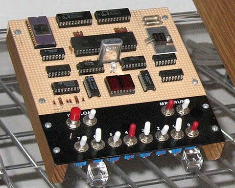
Is anyone using something along the lines of a microprocessor trainer in the classroom today outside a college level EE class?
Personally I can see two general approaches to this, with several possible variations on the two themes. Let's look at them, then I'll go into Blue Sky mode to talk about what I sort of wish for.
Some Ways to Bring Computer Hardware into Class
One is to fake it entirely with present-day hardware. After all, if it's possible to do a complete chip-level simulation of an 8-bit processor in Javascript, it shouldn't be much of a stretch to simulate an entire simple 8-bit microcomputer in a program with the ability to "see" all the operations inside simulated on the screen.
The problem is that this still really fails to make what's being taught "real". To the students, it becomes just another show to watch--one with no particular interest to most of them.
The other approach is to use an actual old microcomputer in class, like the Elf, with the students handling the system, measuring voltages or using logic probes to "see" the signals in the computer. Something more sophisticated would be using chip clips with LEDs on the various lines as a sort of multi-line logic probe. (Here is a place where an Elf or other RCA1802-based system would shine. The 1802 is a fully static processor. It can run at clocks speeds from 0Hz on up to its maximum clock speed, with clock changes on the fly. I have literally clocked 1802 systems by hand by connecting and disconnecting the clock line to +5V and Ground lines, counting out machine cycles as displays show the status of various system lines. There are not a lot of computer systems that can do that!)

Between these two lie many other options. One would be to have a hardware board that connects to a modern computer through a common interface, like USB, where some I/O devices could be visible controlled by the computer (via lights, motors, etc.) and with lines exposed that can safely be probed by the students.
Another would be using a more modern hardware platform, perhaps based on one or more microcontrollers that emulate the function of an older system, exposing such things as memory access, control signals, and so on to the students. The board could include displays and LEDs to show the status of the lines, internal pseudo-registers, and so on. The operation of the entire system, both inside and outside the simulated ICs, could be made available to the student's eyes.
Part of what needs definition is the acceptable limitations of the system. In my own case, I see such a system as being an introduction to low-level hardware operation and control of that operation through software.
Blue Sky Dreaming
If I could have what I wanted without any effort on my part or a significant amount of the school's money, here's what I'd like:
Step 1
I would want to introduce a basic system that's very similar to the original Elf of 1976.
It would have:
Step 2
After the first few lessons, the toggle switches would get old and I'd want to introduce a hexadecimal keypad. This would teach hexadecimal, and continue the association of computer instructions with numeric values in the computer. Presumably the connection between signal levels and numbers has been made using toggle switches.
With the easier input technique, it'd be nice to add some more memory, up to something like 512 bytes to 1 kilobyte.
Step 3
Next, a keyboard would be attached. Perhaps writing software to interface the keyboard to the system would be one of the Step 2 projects. While I'd be tempted to use an ASCII keyboard, I think a raw matrix keyboard would teach more. On this keyboard, machine language instructions and hexadecimal numbers would be mapped to each key. This would again speed programming, and reduce errors. The simple machine language I envision has a particular addressing mode associated with each mnemonic, so there's still no assembling of code required.
Step 4: A larger step
Next, I'd move to a more abstract level. I believe that the activities prior to this point would teach low level operations well enough to take this jump and still be able to show the connection between the two.
For step 4, the computer would get:
The point at this step would be writing high level programs to perform low level actions like those seen in the earlier steps. Seeing line levels and I/O operations performed, using bitwise operators, seeing the signals represented as numbers of various bases within the language (which I'd expect to support at least binary, hex, and decimal for representation and constants.)
Step 5
The final step with the low level computer would be to produce more sophisticated programs. These would be longer programs, probably projects done by groups of students over a few weeks in class. At this point the understanding of the program control structures and data structures should be a bridge to programming in the chosen language directly on the modern computer.
Final Thoughts
These thoughts are somewhat half-baked as they stand. I or someone would have to do some more work to really define this and turn it into hardware and software and a curriculum to go with it. Some points that need considering are the demarcation between this and a robotics class, common in many schools now (including the one at which I teach.) Also, how much class time does this merit? And so on.
Personally I think that using a micro trainer level system is simple enough to be mastered by most middle-school level students. I've got some actual experience with students to back that up, in addition to my own experience (I was 14 when I constructed my own Elf.) For the students, the information not only gives them an understanding of the underlying technologies of current systems, but would open the doors to embedded systems, far more common than conventional general purpose computers. Either way, it would make the computer far less a piece of technical magic controlled by somebody else and far more something comprehensible, and therefore controllable, by themselves.
Some related work--a 4 bit TTL Processor.
The fact is, all the steps above would probably be unnecessary and involve too many changes to the hardware platform to be practical in class. A more reasonable approach would probably be to go from a slightly more capable Step 1 computer directly to Step 4. This would reduce the opportunity for student disorientation as a result of seemingly constant hardware changes, and still be enough to get the key points across.
The activities I envision for Steps 2 and 3 could be either dropped or performed in either the initial or final configuration of the system. This would also simplify the system itself.
Tweet
The place for a small teaching computer, as we're discussing it, lies somewhere between electronics and the standard non-computer science introductory computer programming class. It's a matter of teaching what the components in the system do, and how they do it. This becomes a model of what happens inside more powerful modern computers at larger scale. Such as in current desktops, laptops, tablets, and smartphones.
The COSMAC Elf, this version includes video graphics.
Is anyone using something along the lines of a microprocessor trainer in the classroom today outside a college level EE class?
Personally I can see two general approaches to this, with several possible variations on the two themes. Let's look at them, then I'll go into Blue Sky mode to talk about what I sort of wish for.
Some Ways to Bring Computer Hardware into Class
One is to fake it entirely with present-day hardware. After all, if it's possible to do a complete chip-level simulation of an 8-bit processor in Javascript, it shouldn't be much of a stretch to simulate an entire simple 8-bit microcomputer in a program with the ability to "see" all the operations inside simulated on the screen.
The problem is that this still really fails to make what's being taught "real". To the students, it becomes just another show to watch--one with no particular interest to most of them.
The other approach is to use an actual old microcomputer in class, like the Elf, with the students handling the system, measuring voltages or using logic probes to "see" the signals in the computer. Something more sophisticated would be using chip clips with LEDs on the various lines as a sort of multi-line logic probe. (Here is a place where an Elf or other RCA1802-based system would shine. The 1802 is a fully static processor. It can run at clocks speeds from 0Hz on up to its maximum clock speed, with clock changes on the fly. I have literally clocked 1802 systems by hand by connecting and disconnecting the clock line to +5V and Ground lines, counting out machine cycles as displays show the status of various system lines. There are not a lot of computer systems that can do that!)
Between these two lie many other options. One would be to have a hardware board that connects to a modern computer through a common interface, like USB, where some I/O devices could be visible controlled by the computer (via lights, motors, etc.) and with lines exposed that can safely be probed by the students.
Another would be using a more modern hardware platform, perhaps based on one or more microcontrollers that emulate the function of an older system, exposing such things as memory access, control signals, and so on to the students. The board could include displays and LEDs to show the status of the lines, internal pseudo-registers, and so on. The operation of the entire system, both inside and outside the simulated ICs, could be made available to the student's eyes.
Part of what needs definition is the acceptable limitations of the system. In my own case, I see such a system as being an introduction to low-level hardware operation and control of that operation through software.
Blue Sky Dreaming
If I could have what I wanted without any effort on my part or a significant amount of the school's money, here's what I'd like:
Step 1
I would want to introduce a basic system that's very similar to the original Elf of 1976.
It would have:
- Toggle switch inputs (to associate signals with data and to help teach binary),
- A binary LED display and a two-digit hexadecimal display,
- Very limited memory (about 128 to 256 bytes)(to teach how much can be done in limited memory, and to limit the size of early programs to sane sizes.
- Exposed memory and I/O lines, possibly with LED monitors
- Extra monitors, like maybe dual color LEDs to show data direction on I/O ports, etc.
- A simple machine language with whole-word mnemonics.
- The ability to operate at extremely low clock speeds (0-100Hz) as well as higher speeds (1-10MHz or something like.)
Step 2
- Hexadecimal Keyboard
- 512B to 1024B of RAM
After the first few lessons, the toggle switches would get old and I'd want to introduce a hexadecimal keypad. This would teach hexadecimal, and continue the association of computer instructions with numeric values in the computer. Presumably the connection between signal levels and numbers has been made using toggle switches.
With the easier input technique, it'd be nice to add some more memory, up to something like 512 bytes to 1 kilobyte.
Step 3
- Keyboard with instruction mnemonics and hex digits
- Perhaps more memory, up to about 4K
Next, a keyboard would be attached. Perhaps writing software to interface the keyboard to the system would be one of the Step 2 projects. While I'd be tempted to use an ASCII keyboard, I think a raw matrix keyboard would teach more. On this keyboard, machine language instructions and hexadecimal numbers would be mapped to each key. This would again speed programming, and reduce errors. The simple machine language I envision has a particular addressing mode associated with each mnemonic, so there's still no assembling of code required.
Step 4: A larger step
Next, I'd move to a more abstract level. I believe that the activities prior to this point would teach low level operations well enough to take this jump and still be able to show the connection between the two.
For step 4, the computer would get:
- More memory. Anywhere from 4K to 64K. Perhaps it would start at 4K and grow as the students hit the limitations of each memory size.
- A terminal connection to a current generation computer for keyboard and display, or an encoded keyboard and some other form of text display.
- New firmware (probably activated from on-board with a mode switch), which would provide a fairly sophisticated command line interface with command editing, recall, etc., as well as an interactive programming language. The specific language doesn't matter too much, it could be a BASIC, a bash-alike, a LOGO, or an interactive form of some other compiled language.
- Mass storage. Probably some modern semiconductor memory.
The point at this step would be writing high level programs to perform low level actions like those seen in the earlier steps. Seeing line levels and I/O operations performed, using bitwise operators, seeing the signals represented as numbers of various bases within the language (which I'd expect to support at least binary, hex, and decimal for representation and constants.)
Step 5
The final step with the low level computer would be to produce more sophisticated programs. These would be longer programs, probably projects done by groups of students over a few weeks in class. At this point the understanding of the program control structures and data structures should be a bridge to programming in the chosen language directly on the modern computer.
Final Thoughts
These thoughts are somewhat half-baked as they stand. I or someone would have to do some more work to really define this and turn it into hardware and software and a curriculum to go with it. Some points that need considering are the demarcation between this and a robotics class, common in many schools now (including the one at which I teach.) Also, how much class time does this merit? And so on.
Personally I think that using a micro trainer level system is simple enough to be mastered by most middle-school level students. I've got some actual experience with students to back that up, in addition to my own experience (I was 14 when I constructed my own Elf.) For the students, the information not only gives them an understanding of the underlying technologies of current systems, but would open the doors to embedded systems, far more common than conventional general purpose computers. Either way, it would make the computer far less a piece of technical magic controlled by somebody else and far more something comprehensible, and therefore controllable, by themselves.
Some related work--a 4 bit TTL Processor.
The fact is, all the steps above would probably be unnecessary and involve too many changes to the hardware platform to be practical in class. A more reasonable approach would probably be to go from a slightly more capable Step 1 computer directly to Step 4. This would reduce the opportunity for student disorientation as a result of seemingly constant hardware changes, and still be enough to get the key points across.
The activities I envision for Steps 2 and 3 could be either dropped or performed in either the initial or final configuration of the system. This would also simplify the system itself.
Monday, March 28, 2011
CNC Machine: Microcarve A4
I've been looking at setting up my own CNC machine for about ten years now. I've worked with CNC and CMM machines off and on since the early 80s. I remember hooking up a CP/M computer to a CMM machine, wowing the lab with its ability to automatically record measurements then produce a compliance report on each part as it was inspected. The next day we went back to doing it manually. Everyone was impressed, but they weren't prepared to add computer infrastructure to the lab at that point.
In my case, I wasn't looking to add supporting a CNC machine to my workload before now. Whenever I read the online forums for adding computer control to milling machines, or building up simple hobbyist CNCs, it looked like working on the CNC itself became the prime object of the effort, rather than using the low-cost CNC for production.
There are a lot of bits and pieces to a CNC. There's also a lot of work represented by the physical machine's construction. I'm aware of this from the professional CNCs I've seen at work. They're high precision equipment, with a team of skilled people supporting their operation. Like a machinist, a machinist's assistant, an electronics tech, a programmer at least part time, and a metrology tech or two checking up on it periodically.
As a hobbyist, I have to do bits of all their jobs, plus the jobs of the design engineers, manufacturing engineers, materials engineers, and their technicians to produce things with a home CNC. Needless to say, I won't be trying to do quite the same thing.
I've started by purchasing an existing CNC machine bed rather than trying to design and build my own. I'm also purchasing a commercial motor controller system. My engineer ego is not in the least bit challenged. My engineer superego knows well the tremendous value of the design work that's gone into the pieces. Cookbook integration is good enough for me here. It's the stuff I make with it that I'll set my ego loose on.
The machine I've purchased is a Microcarve A4. The designer did the commercial Fireball V90 previously. The Microcarve A4 is a smaller unit built for high precision. Which suits me perfectly--a specialized machine is just what I'm looking for.
The controller I've purchased is the Gecko 540. It looks like a well integrated unit with a lot of design fine-tuning in it.
Both should arrive soon, the controller (driver in CNC terms) may come tomorrow if the USPS package tracker is telling me what I think it is. I've got a computer running EMC2 that I've been learning how to use to some degree, that I'll hook up the Gecko and motors to once they're here to shake out that element.
I've got some decent software for 2.5 dimensional conversion of images and such (including the image to gcode software included with EMC2), I'm still trying out CAD packages for real 3D work and CAM programs for converting those designs to tool control instructions on the CNC machine. I want to get that all shaken out to make for as little obstruction between idea and finished part as possible.
It'll be an exciting next couple of weeks. I'm looking forward to getting things assembled, functional, calibrated, and churning out parts. With breaks for infrastructure work (like dust/chip collection and an enclosure) between production runs..
Tweet
In my case, I wasn't looking to add supporting a CNC machine to my workload before now. Whenever I read the online forums for adding computer control to milling machines, or building up simple hobbyist CNCs, it looked like working on the CNC itself became the prime object of the effort, rather than using the low-cost CNC for production.
There are a lot of bits and pieces to a CNC. There's also a lot of work represented by the physical machine's construction. I'm aware of this from the professional CNCs I've seen at work. They're high precision equipment, with a team of skilled people supporting their operation. Like a machinist, a machinist's assistant, an electronics tech, a programmer at least part time, and a metrology tech or two checking up on it periodically.
As a hobbyist, I have to do bits of all their jobs, plus the jobs of the design engineers, manufacturing engineers, materials engineers, and their technicians to produce things with a home CNC. Needless to say, I won't be trying to do quite the same thing.
I've started by purchasing an existing CNC machine bed rather than trying to design and build my own. I'm also purchasing a commercial motor controller system. My engineer ego is not in the least bit challenged. My engineer superego knows well the tremendous value of the design work that's gone into the pieces. Cookbook integration is good enough for me here. It's the stuff I make with it that I'll set my ego loose on.
The machine I've purchased is a Microcarve A4. The designer did the commercial Fireball V90 previously. The Microcarve A4 is a smaller unit built for high precision. Which suits me perfectly--a specialized machine is just what I'm looking for.
The controller I've purchased is the Gecko 540. It looks like a well integrated unit with a lot of design fine-tuning in it.
Both should arrive soon, the controller (driver in CNC terms) may come tomorrow if the USPS package tracker is telling me what I think it is. I've got a computer running EMC2 that I've been learning how to use to some degree, that I'll hook up the Gecko and motors to once they're here to shake out that element.
I've got some decent software for 2.5 dimensional conversion of images and such (including the image to gcode software included with EMC2), I'm still trying out CAD packages for real 3D work and CAM programs for converting those designs to tool control instructions on the CNC machine. I want to get that all shaken out to make for as little obstruction between idea and finished part as possible.
It'll be an exciting next couple of weeks. I'm looking forward to getting things assembled, functional, calibrated, and churning out parts. With breaks for infrastructure work (like dust/chip collection and an enclosure) between production runs..
Wednesday, February 16, 2011
R.I.P. HFE Electronics, Sac's Electronic Part Source
I wrote a post about the HFE Electronics Store last year. They took over the former HSC Electronics store here in the Sacramento area. I drove by today, and the store was empty.

It looks like they went out of business two or three months ago, based on their Facebook discussion page. I only got down there four or five times a year, but I usually stocked up on parts, tools, and supplies on each trip.
Unfortunately this leaves me without a local storefront supplier for electronics. Our local Fry's Electronics carries enough in the way of components and such to make up for what Radio Shack dropped from their line a few years ago. But the selection of parts like interconnects, switches, and prototyping components they had at HFE was far greater than I'd expect to find anywhere other than an old-fashioned electronics store.
I do buy a lot of parts online now, I'll admit. I have about two shopping sprees a year for parts from places like The Electronic Goldmine and BG Micro. Not to mention frequent buys of parts from regular suppliers like Jameco, Mouser Electronics, All American Semiconductor.
But there's a difference.
At a local storefront, the parts are in my hands today. Plus, I can see them and handle them. With items like switches this is extremely important. I can also buy parts in small quantities speculatively then come back the next day if they work out and I need more (I've done this several times over the years at HFE/HSC. I remember once buying over $100 more in components on both days than I had planned on buying on each of two consecutive days. As I recall, the main culprit was some displays one the first day, and some uP support chips the second.)
Another thing that's important about local stores is their accessibility to youngsters getting into the electronics hobby. I know that for me when I was young, and now my daughters, fishing through boxes of parts and imagining what could be done with them is very inspirational. A couple of the fellows at the shop I haunted in my teens (Wenger's Electronics in Walnut Creek, CA) mentored me on several of my early projects. Plus there was advice I picked up from other customers. Not to mention that Wengers had a rack of bubble pack parts from Jameco, where I got my first 8080A.
A Long Time Since
I've been shopping at what was HSC and became HFE since I moved to the Sacramento almost exactly 25 years ago. Back then, I lived just a few blocks away. I not only stopped by in the evenings (if I had to run out in the evening for something, hey, HSC was next door to a Circle K store. How convenient is that? Pick up milk and potentiometers on the same trip out!) They had great flea markets on the weekends. You could pick up most of an Altair or IMSAI for a song back back then, enough that a little TLC would get you there (I wish I'd picked up an IMSAI for the front panel.)
There were other electronics stores* in Sac back then, plus I was right at the north end of town so it was easier to get to places like Natomas and Del Paso Heights for those stores. Since I moved to the foothills, HFE has been where I go.
This is where I met Dave Baldwin. I followed him home to get a treasure trove of old computer and parts he was seeking a home for. It's where I picked up about half of my test instruments, in various states of operability, that I use regularly today. It's where I've picked up interesting bits for many projects, and bits that still inhabit my parts drawers awaiting future fun projects.
I'll miss it.
----------------------------------------------------------------------------
Note: If you know something else in the area that I don't seem to know about (I already know about Fry's and Radio Shack, obviously), then drop a comment or an email, please!
*I'm using the term "electronics store" to refer to what I consider to be an electronics store, which is not a place that primarily sells consumer electronics. We used to call those "TV shops" or "Stereo Stores". I'm rather perturbed by such places moving in on the term "electronics store" (though many old-line electronics stores were once TV stores or repair shops.)
Tweet
HFE Electronics. A Valiant Effort, but Now It's Gone.
It looks like they went out of business two or three months ago, based on their Facebook discussion page. I only got down there four or five times a year, but I usually stocked up on parts, tools, and supplies on each trip.
Unfortunately this leaves me without a local storefront supplier for electronics. Our local Fry's Electronics carries enough in the way of components and such to make up for what Radio Shack dropped from their line a few years ago. But the selection of parts like interconnects, switches, and prototyping components they had at HFE was far greater than I'd expect to find anywhere other than an old-fashioned electronics store.
I do buy a lot of parts online now, I'll admit. I have about two shopping sprees a year for parts from places like The Electronic Goldmine and BG Micro. Not to mention frequent buys of parts from regular suppliers like Jameco, Mouser Electronics, All American Semiconductor.
But there's a difference.
At a local storefront, the parts are in my hands today. Plus, I can see them and handle them. With items like switches this is extremely important. I can also buy parts in small quantities speculatively then come back the next day if they work out and I need more (I've done this several times over the years at HFE/HSC. I remember once buying over $100 more in components on both days than I had planned on buying on each of two consecutive days. As I recall, the main culprit was some displays one the first day, and some uP support chips the second.)
Another thing that's important about local stores is their accessibility to youngsters getting into the electronics hobby. I know that for me when I was young, and now my daughters, fishing through boxes of parts and imagining what could be done with them is very inspirational. A couple of the fellows at the shop I haunted in my teens (Wenger's Electronics in Walnut Creek, CA) mentored me on several of my early projects. Plus there was advice I picked up from other customers. Not to mention that Wengers had a rack of bubble pack parts from Jameco, where I got my first 8080A.
A Long Time Since
I've been shopping at what was HSC and became HFE since I moved to the Sacramento almost exactly 25 years ago. Back then, I lived just a few blocks away. I not only stopped by in the evenings (if I had to run out in the evening for something, hey, HSC was next door to a Circle K store. How convenient is that? Pick up milk and potentiometers on the same trip out!) They had great flea markets on the weekends. You could pick up most of an Altair or IMSAI for a song back back then, enough that a little TLC would get you there (I wish I'd picked up an IMSAI for the front panel.)
There were other electronics stores* in Sac back then, plus I was right at the north end of town so it was easier to get to places like Natomas and Del Paso Heights for those stores. Since I moved to the foothills, HFE has been where I go.
This is where I met Dave Baldwin. I followed him home to get a treasure trove of old computer and parts he was seeking a home for. It's where I picked up about half of my test instruments, in various states of operability, that I use regularly today. It's where I've picked up interesting bits for many projects, and bits that still inhabit my parts drawers awaiting future fun projects.
I'll miss it.
----------------------------------------------------------------------------
Note: If you know something else in the area that I don't seem to know about (I already know about Fry's and Radio Shack, obviously), then drop a comment or an email, please!
*I'm using the term "electronics store" to refer to what I consider to be an electronics store, which is not a place that primarily sells consumer electronics. We used to call those "TV shops" or "Stereo Stores". I'm rather perturbed by such places moving in on the term "electronics store" (though many old-line electronics stores were once TV stores or repair shops.)
Wednesday, June 30, 2010
Retrocomputing Summer
Aside from some astronomy, I've been spending a lot of my free time this summer on some retrocomputing projects. In particular, I've been working on my homebrew 8085 single board computer and my Ampro Little Board Plus Z-80 systems. Alongside that, I've been trying to fit a new computer that's similar to a COSMAC Elf into an Altoids tin.

Retrocomputing in Your Pocket.
Meanwhile, I'm trying to fit my Membership Card into its tin. I think my switches are too tall, so I'm going to have to make some other accomodations.
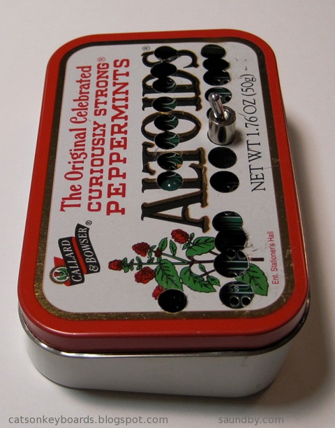

Each step of the project adds just one to three new pieces to the computer. The complete computer is only twelve integrated circuits, plus resistors, capacitors, and other small parts. It can be built with only eight ICs, if you want a simpler version that gives up a couple of extras. These can always be added in later, if desired. The real key to the project is that it provides a complete, functional 8085 system similar to the SDK-85 development system that can be built up from simple parts that are easy to understand and use in programs.
Most of my work lately, other than playing with software and deciding how I want the programmer's interface to work in its operating system, has been on the front panel of the computer and its enclosure. I want it to be something that someone with minimal tools, and even without power tools, can build from common materials available at an ordinary hardware store. I also want it to be attractive enough to show off after it's built, not something that looks like it belongs in a junkpile.

Since posting details on the 8085 construction project takes about 3 times as long as doing it, I've been holding off on doing an update of the project on its site until I have the enclosure complete. Now I'm almost done, so an update will probably occupy the later part of my summer.

I got a pair of system boards for these from Dave Baldwin when he was cleaning out some old computers prior to a move. One night, I really wanted to get one of the many systems up and running that Dave had given me, and since these seemed like they'd be the easiest to get running I grabbed one and got it going.


Then Vic Maris of StellarVue Telescopes offered me an old desk he didn't need at his offices any more. He said it was large. It is. I had to do some major work to get it into my office. But once there, I put my usual computers on it (an iMac 20" and a Beige G3 PowerPC Mac), and had enough room for one more computer!

I put the Ampro's current box (a PC's beige box) under the desk. I've got another enclosure for it that'll be much more attractive and interesting--but that's another project yet to come. On top, I had plenty of room for my ADDS 2020 terminal, which is the user interface for the Ampro. Unlike the original Big Board computer (the "Ferguson"), the Ampro uses a terminal, whereas the Big Board has a built in CRT and keyboard interface.
Once I got everything in place, I started working with my ADDS terminal to try to get the best image out of it. I originally used this terminal with the Ampro because it's the smallest full terminal I've got. I took a look at all the space on my new desk, and realized...I could use a better terminal. So I pulled out my VT-102, which has a very nice white on black character display and is very sharp.

The VT-102 wasn't perfect, though. So, thanks to some help from fellow retrocomputerists I was able to find the technical info I needed to adjust the character height on the display (it was a little taller in one part than another when it came out of the garage.) Now it's perfect.
Now I'm happily writing games in Turbo Pascal at my desk, and the space next to my easy chair is waiting for another project to move in while my wife's back is turned.

Since this picture was taken I've cleaned up. Really.
The breadboard version of my 8085 computer, the MAG-85 is still in use, by the way. That's where I've been doing my OS development while I finish the permanent version of the hardware. That way I don't have to worry if I've got the permanent one's keyboard and display off for work on the face panel if I want to sit down and code some 8080/8085 assembly.
Lee Hart's 1802-Based Mini-Microcomputer: The Membership Card.
Retrocomputing in Your Pocket.
Lee Hart's Membership Card computer. It's based on the RCA 1802 microprocessor, and it's a close cousin to the COSMAC Elf computer (Google it, if you don't know about it!)
Meanwhile, I'm trying to fit my Membership Card into its tin. I think my switches are too tall, so I'm going to have to make some other accomodations.
The tin doesn't quite close up. My interconnect between the PCBs may be too tall, or my switches aren't laying as low as Lee's did. It's only about 1.5mm, but it's enough. I'm working on Plan B now.
My 8085 Handheld Single Board Computer Project
My first shot at a front panel layout for my 8085 computer, laid out on acrylic sheet to make it easy to see what's where.
Each step of the project adds just one to three new pieces to the computer. The complete computer is only twelve integrated circuits, plus resistors, capacitors, and other small parts. It can be built with only eight ICs, if you want a simpler version that gives up a couple of extras. These can always be added in later, if desired. The real key to the project is that it provides a complete, functional 8085 system similar to the SDK-85 development system that can be built up from simple parts that are easy to understand and use in programs.
Most of my work lately, other than playing with software and deciding how I want the programmer's interface to work in its operating system, has been on the front panel of the computer and its enclosure. I want it to be something that someone with minimal tools, and even without power tools, can build from common materials available at an ordinary hardware store. I also want it to be attractive enough to show off after it's built, not something that looks like it belongs in a junkpile.
The partially-complete Masonite face panel of my 8085 computer.
Since posting details on the 8085 construction project takes about 3 times as long as doing it, I've been holding off on doing an update of the project on its site until I have the enclosure complete. Now I'm almost done, so an update will probably occupy the later part of my summer.
Ampro Little Board Plus Z-80
My Ampro Little Board Plus, in its original incarnation. A pile of parts on a kitchen table.
I got a pair of system boards for these from Dave Baldwin when he was cleaning out some old computers prior to a move. One night, I really wanted to get one of the many systems up and running that Dave had given me, and since these seemed like they'd be the easiest to get running I grabbed one and got it going.
A complete computer, with Z-80 CPU at 4MHz, Floppy Disk Drive Controller, Serial and Parallel I/O, and SCSI all on one small card--in 1984!
Honey, how about we eat dinner on the patio tonight?
Then Vic Maris of StellarVue Telescopes offered me an old desk he didn't need at his offices any more. He said it was large. It is. I had to do some major work to get it into my office. But once there, I put my usual computers on it (an iMac 20" and a Beige G3 PowerPC Mac), and had enough room for one more computer!
My new desk, with Three full size computers.
I put the Ampro's current box (a PC's beige box) under the desk. I've got another enclosure for it that'll be much more attractive and interesting--but that's another project yet to come. On top, I had plenty of room for my ADDS 2020 terminal, which is the user interface for the Ampro. Unlike the original Big Board computer (the "Ferguson"), the Ampro uses a terminal, whereas the Big Board has a built in CRT and keyboard interface.
Once I got everything in place, I started working with my ADDS terminal to try to get the best image out of it. I originally used this terminal with the Ampro because it's the smallest full terminal I've got. I took a look at all the space on my new desk, and realized...I could use a better terminal. So I pulled out my VT-102, which has a very nice white on black character display and is very sharp.
The Beige G3 runs Lemmings and Warcraft, the iMac is my interwebs machine, it's desktop background is an image of the Big Board computer PCB, and to the right is my Ampro's terminal, here showing the utilities menu.
The VT-102 wasn't perfect, though. So, thanks to some help from fellow retrocomputerists I was able to find the technical info I needed to adjust the character height on the display (it was a little taller in one part than another when it came out of the garage.) Now it's perfect.
Now I'm happily writing games in Turbo Pascal at my desk, and the space next to my easy chair is waiting for another project to move in while my wife's back is turned.
Getting the new desk in meant moving some stuff out.
Since this picture was taken I've cleaned up. Really.
The breadboard version of my 8085 computer, the MAG-85 is still in use, by the way. That's where I've been doing my OS development while I finish the permanent version of the hardware. That way I don't have to worry if I've got the permanent one's keyboard and display off for work on the face panel if I want to sit down and code some 8080/8085 assembly.

Subscribe to:
Posts (Atom)


 Posts


 Webomator.com: Backward into the