Showing posts with label assembly language. Show all posts

Wednesday, August 15, 2012

Parallax Propeller + COSMAC 1802: the Saga Continues...

Monday morning I posted about hooking up a Parallax Propeller QuickStart Board to an 1802 Microprocessor. My hopes are to make the Propeller behave as a RAM for the 1802, primarily to be able to display a bitmap of that segment of memory as video. The idea is to make it compatible software-wise with the 1861 Pixie chip (the 1802's native video adapter), which is presently unavailable.

Since then I've spent more time on this project. A lot of that time got tied up in side issues related to tying a Propeller to an 1802, as well as some time spent dealing with the test equipment I want to use to keep an eye on the circuit and see what it's up to.

First, here's how it looks tonight:

Propeller QuickStart hooked up to an old CDP1802 microprocessor.
The second stage of the Propeller/1802 mashup circuit. Click for full size.
I've got a closer relationship between the two processors now. The Propeller is actually doing something. Before, the 1802 was getting power and a fixed clock signal off the QuickStart board, but the Propeller was not itself involved.

Clocking the 1802
One thing I put a fair bit of time into (too much, that is) is using the Propeller to control the clock of the 1802. There are a few reasons I think this would be nice:

The clock can be varied in software depending on the user's desire and the individual 1802's capabilities.
At some later point, the Prop can have a greater degree of control over the 1802's operation in general. With the ability to stop it, start it, and even single-step it.

On my first stab at this a couple of days ago, I just threw a repeat loop into the Prop's code to pulse an output line. I didn't have very good control of the rate, I didn't have the constants set right, and it didn't work right off the bat so I decided to drop it and just use another clock.

Let's Try a Timer, Because...That's What They're For
This time I took time to read up on using the counter/timers on the Prop. Each cog has one, and I played around with it for a while before feeding its output to the 1802's clock input. After a while I was able to get the results I wanted, and was able to fine-tune that bit of the code.

Then I hooked it up to the 1802 with a frequency of 1.25MHz...well, I should say I hooked it up to a 4049, passed it through a pair of inverters to square it up a bit and buffer it. Then I passed the signal to the 1802. Which ran just fine.

At this point I still had the data bus of the 1802 hard wired to a $C4, which is a NOP instruction for the 1802. That way I can watch LEDs on the address bus and see that the chip is running through its address space. The pulse rate of the high order LED gives me an immediate idea of how fast the 1802 is getting clocked, too.

Then I started playing with the constant for the counter's frequency to see what speeds this 1802 chip would be good at with a 5V Vdd and 3.3V Vcc (the 1802 can use split supply voltages for its core and I/O. Not bad for 1976, eh?)

Overclocking! 4.8MHz Baby! Yeah, uh, Megahertz.
This one ran up to 3.6MHz without a problem. I didn't run it up until it stopped, the other day I think I had it running at about 4MHz when I was playing with the repeat loop. Above 3.6MHz it seemed to start running hot, so I stepped it back down again.

Above 3.6MHz it was noticeably warm after a while, and seemed to be getting warmer. Between 3.2 and 3.6MHz it was warm, but maintaining its temperature just fine. At 3.2MHz it was solid as a rock and the heat was barely detectable to a calibrated fingertip. If I can get it to run at this speed reliably with the Propeller providing video then popular Elf software like Tiny Basic, Forth, CHIP-8, and the programs written in them are going to rock on this system.

Edit: I've run it up to 4.807MHz now, and it didn't seem all that hot this time. It really shouldn't have any problem with heat at these voltages, it normally runs at 5MHz at higher voltages. And now it doesn't seem to have a problem. When I tried to take it over 4.8MHz it ran sometimes but not others, or hung occasionally. So this is the limit for stable operation at this voltage for this chip (an RCA CDP1802CE.)

Getting Data to the 1802

OK, so back to the problem of making the Propeller look like a RAM. Frankly, when I did my first look at the timing involved, I figured this would be completely trivial to implement. Push in data and address bus wires, connect up /MRD (memory read signal) from the 1802 to the Prop, crank a little Spin code, and I'd have the Prop acting like a ROM.

Put in /MWR and a little more code, BAM, the Prop is a RAM.

Hook up TPA to catch the high order address byte, tweak the code, and the Prop is ready to map more than 256 bytes. All I'd have to do is add the video code then figure out how much Prop RAM was available then expand to fit.

Well, it wasn't that easy. If it had been, I'd be playing with the video now.

I tried to leap forward at first. I plugged in the address and data bus wires, plugged in /MRD, and added some code to my clock driver program. It had a 256 byte array that it set up and initialized to $C4 in every position (NOP again, but this time it would be a soft NOP rather than a hard-wired one.) Then I wrote the program to wait for the Propeller I/O line I'd selected for /MRD to go low. Once that happened, it would get the address off the address bus, look up the appropriate element in the RAM array in memory, and put it out on the data bus until /MRD came back up again.

Easy-peasy, right?

Well, it didn't work.

Oscilloscope signal trace of one of the data lines and /MRD on the Propeller/1802 mashup.
Top: Data from Propellor pretending to be a memory. Bottom: Memory Read Request. Result: Memory Too Slow! (Click for full size.)

When I was doing my timing calcs and looking at the 1802's leisurely timing--it doesn't mind waiting just under a millisecond for its memory to come back when it's running at its normal speed (about 1.78MHz.) Hey, an 80MHz processor could be running a version of interpreted BASIC written in LISP and keep up with that, right?

I guess not. At least not the way I did it.

I clocked the 1802 at 1.25MHz for the test. This is an easy, slow speed that the Propeller can generate easily. I figured it'd work, I'd push up the frequency to 2.5MHz, check timings on the scope, and discover that I couldn't make the 1802 go too fast for the Prop.

Unfortunately the trace above shows different.

I Can Do Lots of Things Wrong, All at Once
I'm sure this is the result of something I'm doing improperly. I can think of several possibilities already:

I'm using WAITPNE and WAITPEQ to respond to the pin change. Perhaps, because they do some power-saving activity on the cog on which they're invoked, they just aren't meant to respond this quickly. Maybe if I just go to an active polling loop I'll be OK?

I'm using SPIN, an interpreted language. Perhaps I need to just insert a bit of Propeller assembly to tighten up the timing?

Perhaps there's some option or configuration thing I've not done?

Maybe this cog has to do something active with the timer/counter (I'm using the same cog as the one that's running the 1802's clock.) Perhaps if I move the RAM functions to another cog I'll be fine?

Those are just what comes off the top of my head. I'm far from being an expert on the Propeller, and I haven't picked up the books on it yet, just the free manual and datasheet downloads. But things like this create an opportunity to learn.

I also had a few other things I needed to figure out on the way, minor little things like the order you mention the output pins in when writing your code statements (I was getting $23 out instead of $C4 initially. Yeah, oops.) That and the whole thing is a rather fragile lash-up right now. I'm going to go to solder as soon as I get the RAM moving data to and from the 1802. But not before, because I hate rework, and if I don't test it on a breadboard first, there'll be rework. And this lets me do a few things like change which lines I'm using for address and data easily. I moved the data lines to P16..23 so that I can watch the data on the QuickStart board's LEDs, like a little front panel. Before, I had the address lines here, but I've already got LEDs on the breadboard showing me the address line states. So a quick change of a few constants in software, and I get a data display with no re-soldering.

Slightly Off-Task Tasks
I also took some time out to search out a line cord for the new frequency counter I got at the Ham Radio Club night before last that didn't have one (found one, after searching high and low. It's an oddball, not an HP cord.) And I checked out the two portable NonLinear Systems oscilloscopes I bought, too (one works, one doesn't, as expected.) The frequency counter was very nice to have while I was figuring out how to use the Prop's counter/timer as a numerically controlled oscillator, so the time was well spent even if it did eat into my Propeller-as-RAM time.

Looking Forward to Round 3
I'll be back at this before the end of the week (I'd like to tomorrow, but it'll be a busy day so I may not be able to.) If you have any suggestions or salient experience, your comments or emails would be much appreciated!

Edit:

I've had a look at the Propeller docs. It looks like the timing of hub instructions is my problem. I may just insert WAIT states for the 1802 and see what that does.

Thursday, July 19, 2012

8085 Monitor Code and Other Distractions

I've been working on an 8085 microprocessor project for about 3 years now. It started with a simple circuit on a breadboard, moved to my HP Logic Lab, where it became a real computer, then got built into a permanent version on a prototyping PC board.

I've been documenting the thing since it moved to the Logic Lab on my web site, posting how-to articles on building both versions (the hardware is identical, only the construction method is different), as well as software to control the hardware.

Where I've come up short is putting together a sort of unified OS for the system online that allows software to be developed right on the system itself, as well as any high level languages. I've been writing lots of software for my own use with the system, mostly hand-coded using my assembly coding forms and my 8085 Pocket Reference Card. But I keep either getting distracted from or otherwise dodging the job of integrating all the software bits I've already got into a simple "monitor" program (sort of a mini-OS for machine language) for the system.

Part of it is the usual life distractions. I've been sitting next to a wild fire this past week, for example. And then I've got lots of other electronic toys I like to spend some time with. Each one has its own appeal.

Before the fire, and a bit during (when I was taking a break from cutting ever more brush around my property) I've gotten back to work on putting it together. The biggest part is the part that reads the keyboard, determines the current system state, and dispatches keystrokes and execution to the right place. All the hardware interfaces are already in place, most of the basic system routines are in place (timing/delays/string handling), etc. So the "glue" is pretty much all that's needed. And I got it about halfway done before the fire started, I'm writing the code that actually takes actions for each mode, or simply hands over the necessary info to user apps running on the system.

So, if I can get time away from deck repairs on my house this weekend (now that it looks like it's unlikely to burn down or that I get evacuated), I'll be trying to wrap up and test that code.

Small Thing, Big Obstacle

The other thing I'm looking forward to is replacing some of the switches I put on the MAG-85. I put in switches for various interrupts about two years ago, and the switches themselves turned out to bounce and make so much noise that I've given up on them. No amount of debouncing, hardware or software, within reason has made them reliable. I'd hate to have someone else construct a MAG-85 and have to deal with this. It's been a thorn in my side ever since I added them, and took a lot of the fun out of the permanent hardware project for me (on the breadboard version, I used some old keyswitches out of a knackered Mac Plus keyboard, they worked great with only the most minimal hardware debounce. But I figured I could hardly specify 25 year old keyswitches in a project that others might want to build.

I'm expecting a shipment of a bunch of different switches tomorrow that I can test and select from to replace the awful switches I have now. So I can put that behind me (and probably re-simplify the circuit to take out a bunch of the extra parts I put in to try to deal with the noise on these switches.)

Frankly, the old switches are something I'd about hesitate to use in a doorbell circuit, never mind real electronics.

Monday, January 16, 2012

8085 Resurgent: Back to the MAG-85

I took a look at my own website the other day and realized it's been far too long since I have updated certain items there. Most noticeable to me was my MAG-85 project, an 8085-based micro trainer. There are a bunch of things I thought I'd posted over a year ago, but the information isn't there.

Obviously I never did it. Sorry about that.

The front page image for the 8085 project is was a really ugly thing I took at a very interim stage while I was doing regular updates on the project. If I wanted to scare someone off the project, I think that picture is what I'd use. What a rat's nest!

8085 microprocessor computer project SDK-85
A Very Ugly Looking 8085 Computer

Shortly after that picture was taken I built a real front panel and enclosure. It's been happily living in that enclosure for well over a year, but I never posted the info on it. In fact, I've just started taking it apart in preparation for making some improvements. Since I like to take pictures of my work for documentation purposes (like getting the right connectors back in the right places), I took some photos of the partially-disassembled unit as it is before I make the updates. Here's one:

MAG-85 8085 computer project in (and partially out of) its enclosure.
A bit ugly with the top and bottom panels off, connectors and wires trailing out, but not so bad at the first photo.

Here you can see that it's not so ugly as before. The LED to the left of the LCD display is controlled by the 8085's SOD output. The eight LEDs below the display are controlled by the 8085's OUT 01 command and held in their state by a register. The eight switches below that are on the 8085's IN 01 port.

The program that's running currently reads the position of the switches and outputs a byte to the LED bank to match what it sees on the input. It also reads the keyboard and sends the ASCII + 0x30 character to the screen that it reads from the keyboard (which is in IN 00). The LCD display is on the OUT 00 port.

The four push buttons above the keyboard are, from left (red) to right:
RESET
TRAP
RST7.5
RST5.5

In the crude OS/monitor I have running on the MAG-85 now, TRAP acts as an "Escape" key that returns control to the OS. This allows miscreant programs to be stopped and memory examined any time, since TRAP isn't maskable.

RST7.5 is used as the user vector to the start of the application program in memory. In essence, this is the "GO" or "Execute" button.

RST5.5 is also a user vector that should point to a subroutine that does something and returns. Either the application program should initialize it, or it has to be initialized by hand in the monitor.

The keyboard itself uses RST6.5 to read a key value into a buffer, where an OS routine can pick it up/translate it, etc. The keycap legends allow for several uses of the keys. The typical use of the yellow keys is hexadecimal number entry. But they can also be used as arrow keys and fire button (9) for games.

The top row has the IN or Enter key in red, the backspace (BK) in blue, the (M) mode and edit/view (e/v) keys in gray. The edit/view key toggles a flag in the OS that switches between a memory protecting mode (view) and editing mode in the various modes. The mode key modifies the mode variable in the system to switch between Memory, Register, and I/O port viewing or editing. It's possible to change from editing to viewing and back again while in any of the modes.

Current Rework
My current plans for reworking the MAG-85 have to do with replacing the buttons used for RESET, TRAP and the RSTs, plus improving the ergonomics of the unit a bit by replacing the top and bottom panels, which were hand-made on hardboard, with some nicer CNC'd panels that reposition some of the controls (I switched off the unit more than once when I meant to switch on or off the backlight for the LCD.)

The four pushbuttons above the keyboard are some really awful buttons. They ring like bells, causing all sorts of debounce problems. I have both hardware and software debouncing on them right now, and it *mostly* works. I think part of why I stopped posting before was that I wanted to kill this problem before I posted, so as to avoid causing anyone else the headaches I've had with these switches. And, as you can see, those switches are still in there.

A sideline on the current work is also preparing for a couple of improvements that have been planned since the beginning, but haven't happened yet. One is to put a nice little door in so that the NOVRAM/EEPROM/EPROM memory can be swapped out without opening the whole unit. Right now I unscrew the end pieces then pop out the face panel to get at the memory socket. Which is not clean, quick, or easy. I have to get the cables all to go back to their places each time I put it back together. A couple of times I've pulled out one of the input cables by accident, then wondered why the keyboard or switches aren't talking when I get it back together.

The other is preparing to mount a battery pack inside, so that I can go cordless with this thing. A lot of what I've been doing in design tweaks is reducing the power used by the system. Finding a good brightness for the backlight, putting a switch on the backlight so that I can turn it off when I'm in good light, reducing the brightness of the power LED and the I/O LEDs, that sort of thing. As well as looking at my nascent OS to see if there are things I can do there that will reduce power while staying out of the way of the user's programs.

I'm also planning on adding another memory socket for an EPROM. It won't have a ZIF socket in it like the one that's there now, but I'm getting to the point of wanting a more permanent memory for the OS, with the NOVRAM left for user space programs. This may involve some rejiggering of the memory map, since for mechanical reasons I'd like to have the removable memory in the center of the PCB side to side.

I'm also looking at adding an expansion port or two on the new end plates, which begs the question of whether to use a standard connector with a more or less standard wiring for the port (like a PC's bidirectional parallel port) or whether to roll my own for the sake of less constraint on how the lines are used. Basically just bringing the lines from the I/O buffer registers straight out of the box along with power and ground. This is my preference for a number of reasons, but there's an appeal to letting the MAG-85 drive standard I/O devices, too.

The addition of a serial port, either at TTL levels or a standard RS-232C port is another possibility I keep playing with. I've kept SID available for this possibility, though I was tempted to use it as either a user digital I/O or a memory bankswitch I/O or something of the sort. Being able to connect the MAG-85 straight to a terminal would be really nice, so I'm leaning toward an RS-232C port.

But if I do that, I'll need a separate set of I/O routines for that port that allow it to be the primary user I/O for the OS. So if I do that, it'll probably be deferred until some other things happen first.

Like finishing the OS well enough to post it.

Finishing the MAG-85 Operating System
I haven't posted the OS yet because it's still in a fairly yucky developmental state. That and my test hardware still has the crummy switches that do nasty things to me at times, and there's lots of code in the OS just to try to deal with them that can probably come out once I've got decent switches in.

So my present software objective is to clean up the OS and put a bow on it so that I can "ship" it to a download on my site. I may end up cutting some of the features, but there's also the possibility that I'll end up cleaning them up because I've already got too much other code running around that uses them. The core basics are the ability to view and edit the system's memory, and execute a program starting at some given address. I'll guarantee that much.

I think the ability to view and edit register values is pretty well sewn, too. It's possible to bork the OS by doing something stupid here, but I'm not trying to protect the user from being stupid. Press TRAP (probably to be labelled ESC) and the OS will restart and reset any values it needs to function (I hope!)

The ability to view inputs and edit outputs interactively shouldn't be a problem, either, but it's not an immediate priority. If it happens effortlessly, it'll be in the initial release. Otherwise, I won't hold up the release for it.

I've also got another mode that is enabled in some versions for viewing/setting user variables in the OS, such as the RST5.5 and RST7.5 vectors, selecting different display formats, setting the size of the LCD, and so on. I can pretty well guarantee that the full-up version of this will not be in the initial release, though a cut-rate version of it may be. That would mean that you would set these variables yourself when putting the code on your own MAG-85.

If I do go to a design that uses two memories, one rewritable in system and the other not, I'll have to put these variables in RAM, or expect that they be set once and for all in the firmware. I'd like to be able to provide an EPROM at some point for people who want to build a MAG-85 and get up and running without having to put the OS in themselves. But if I do, I either need to put some system information in the NOVRAM memory space (like the height/width of the LCD display) or require that only one size of LCD be used with a specific version of the OS. Since I'm looking forward to building another MAG-85 with a larger display (perhaps 32 characters wide by 4 lines high), I'd like to keep the OS flexible. The initial display routines will only use a portion of displays larger than 20x2, but the user programs can use the larger displays and the OS can be updated later to have multiple display formats that the user can select.

But right now, I just need to drive a stake through its heart and get a workable version out the door. :)

Friday, April 22, 2011

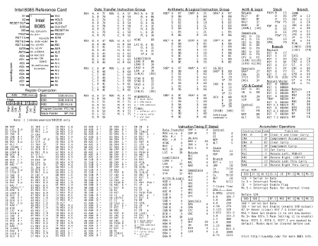
8085 Microprocessor Reference Card Posted

8085 processor reference card

I put up a downloadable PDF of my own 8085 reference card on my website:
8085 Microprocessor Reference Card

I've added a bunch of information that I often use that's not on the original Intel reference card. This includes the undocumented 8085 instructions, timing for all instructions in T-States, a pinout and basic electrical reference, and a little more detail on the additional interrupts the 8085 adds to the 8080A design. Such as the fact that they're off by default, which I've forgotten at least a couple of times when writing test routines.

The card is laid out so that it can be printed on either a single-sided sheet or double sided to make two cards laid out with a front and back. The finished card looks great on a good cover stock paper, and folds to fit nicely into a pocket.

Monday, February 7, 2011

Coding Forms for Hand-Made Programs


I've posted some of the coding forms I use on my website.

For me, hand coding and hand assembling software is pleasant and relaxing. It's like crochet or embroidery (I do both of those as well as programming.) Something as simple as a printed form makes it nicer, neater, and faster.

The forms of my own I've posted are generic assembly language forms. I've also posted a TI 960/980 assembly language form as well as some programming forms for the HP-41C, HP-67 and HP-97 that I use with all of my programmable calculators (like my HP-35S.)