
Free Run Mode on the MAG-85 Trainer Under Construction
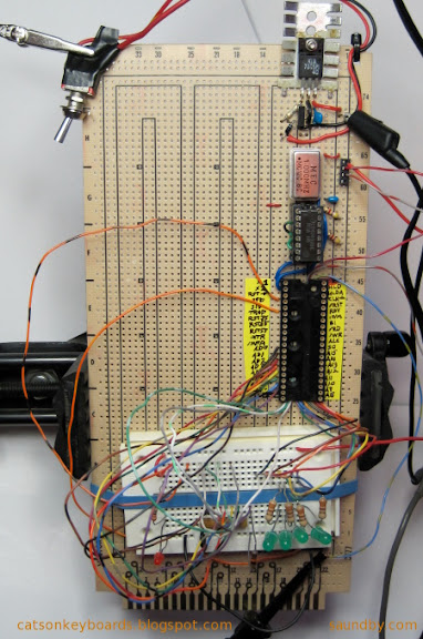
Above is the permanent version of the 8085 trainer I'm building up. I did a "free-run" test with it today, you can see it wired up for that in the image above.
You can read about how to build your own on my 8085 Trainer Project Page on my website.
What you're seeing above is a prototyping printed circuit board with the beginnings of a microcomputer system built up on it. For this test it's got some components on a small solderless breadboard, which is temporarily held on the printed circuit board with a rubber band. The permanent hardware on the board starts at the upper left, where the power supply resides above the shiny metal can. The shiny metal can is the crystal oscillator, which provides the basis of the clock for the 8085 microprocessor. Beneath that is a 4049 chip, which has six inverters in it. Two of these are used for this test, for the 8085's clock, and their output is on the blue wires that go from the 4049 to the big chip, which is the 8085 microprocessor.
In the "free-run" test, the 8085 is tricked into thinking its entire memory is filled with zeros, which translates into "No Operation" or NOP instructions. This makes the 8085 step through its entire memory space. The top four memory address lines of the 8085 are hooked up to LEDs, which blink as the 8085 goes through its memory space. They blink in a pattern that makes it easy to see that the 8085 is doing what it's supposed to do.
The permanent version of this circuit is being built up in the same way I built up the prototype, except that I had to build up a power supply, and of course the permanent version is soldered rather than solderless (except for the temporary test components, as you see in the image.)
Whew!
It's very nice to get to this point and have everything work. When you don't have a custom-made printed circuit board, it's very easy for a lot of things to go wrong. Now I know that my power supply and clock circuits are good, and that I've got the basic wiring for the CPU correct. I've had projects like this crash and burn in the past because I jump in and wire up everything, rather than going forward a bit at a time, testing each section as its added. Even in cases where all the wiring rings out good, and there's no obvious problems when testing before installing the chips in the sockets, I've had small systems refuse to run or refuse to run reliably when assembled.
The circuit is checked out step by step before the 8085 CPU is inserted by probing the 8085's pin positions to make sure the correct voltages and signals are in place.
Now I do things one piece at a time and deal with the fact that getting a working system means spending twice as long in assembly and test as plunging forward headlong and hoping for the best.
For example, in these pictures you can see the guides I put on tape for the pins of the 8085. This makes it a lot easier for me to get the wires in the right places. I also have the 4049 on a little jig to tie its unused inputs to ground until I'm ready to use them. This takes extra time, but lets me isolate different sections of the circuit as I build them, rather than having to build up the whole computer as a piece in order to keep the extra inputs from floating, and potentially causing trouble.
Besides, the build-up and testing is part of the fun of a project like this. No point in rushing past part of the fun. Making something like this is like a crafts project. If you don't enjoy needlework, you're better off buying finished works rather than making your own. The same goes with microcomputer systems.
Other posts on the 8085 Trainer I'm building:
8085 Project Update
8085 Prototype Hardware Complete
8085 Trainer Project
8080A CPUs from NTE (illustration of 8085 Free Run Circuit)
8085 SDK-85 Homebrew Style
Also see:
The MAG-85 Trainer Project Site


 Webomator.com: Backward into the