I've been working on an 8085 microprocessor project for about 3 years now. It started with a simple circuit on a breadboard, moved to my HP Logic Lab, where it became a real computer, then got built into a permanent version on a prototyping PC board.
I've been documenting the thing since it moved to the Logic Lab on my web site, posting how-to articles on building both versions (the hardware is identical, only the construction method is different), as well as software to control the hardware.
Where I've come up short is putting together a sort of unified OS for the system online that allows software to be developed right on the system itself, as well as any high level languages. I've been writing lots of software for my own use with the system, mostly hand-coded using my assembly coding forms and my 8085 Pocket Reference Card. But I keep either getting distracted from or otherwise dodging the job of integrating all the software bits I've already got into a simple "monitor" program (sort of a mini-OS for machine language) for the system.
Part of it is the usual life distractions. I've been sitting next to a wild fire this past week, for example. And then I've got lots of other electronic toys I like to spend some time with. Each one has its own appeal.
Before the fire, and a bit during (when I was taking a break from cutting ever more brush around my property) I've gotten back to work on putting it together. The biggest part is the part that reads the keyboard, determines the current system state, and dispatches keystrokes and execution to the right place. All the hardware interfaces are already in place, most of the basic system routines are in place (timing/delays/string handling), etc. So the "glue" is pretty much all that's needed. And I got it about halfway done before the fire started, I'm writing the code that actually takes actions for each mode, or simply hands over the necessary info to user apps running on the system.
So, if I can get time away from deck repairs on my house this weekend (now that it looks like it's unlikely to burn down or that I get evacuated), I'll be trying to wrap up and test that code.
Small Thing, Big Obstacle
The other thing I'm looking forward to is replacing some of the switches I put on the MAG-85. I put in switches for various interrupts about two years ago, and the switches themselves turned out to bounce and make so much noise that I've given up on them. No amount of debouncing, hardware or software, within reason has made them reliable. I'd hate to have someone else construct a MAG-85 and have to deal with this. It's been a thorn in my side ever since I added them, and took a lot of the fun out of the permanent hardware project for me (on the breadboard version, I used some old keyswitches out of a knackered Mac Plus keyboard, they worked great with only the most minimal hardware debounce. But I figured I could hardly specify 25 year old keyswitches in a project that others might want to build.
I'm expecting a shipment of a bunch of different switches tomorrow that I can test and select from to replace the awful switches I have now. So I can put that behind me (and probably re-simplify the circuit to take out a bunch of the extra parts I put in to try to deal with the noise on these switches.)
Frankly, the old switches are something I'd about hesitate to use in a doorbell circuit, never mind real electronics.
Showing posts with label 8085. Show all posts
Showing posts with label 8085. Show all posts
Thursday, July 19, 2012
Monday, January 16, 2012
8085 Resurgent: Back to the MAG-85
I took a look at my own website the other day and realized it's been far too long since I have updated certain items there. Most noticeable to me was my MAG-85 project, an 8085-based micro trainer. There are a bunch of things I thought I'd posted over a year ago, but the information isn't there.
Obviously I never did it. Sorry about that.
The front page image for the 8085 project is was a really ugly thing I took at a very interim stage while I was doing regular updates on the project. If I wanted to scare someone off the project, I think that picture is what I'd use. What a rat's nest!

Shortly after that picture was taken I built a real front panel and enclosure. It's been happily living in that enclosure for well over a year, but I never posted the info on it. In fact, I've just started taking it apart in preparation for making some improvements. Since I like to take pictures of my work for documentation purposes (like getting the right connectors back in the right places), I took some photos of the partially-disassembled unit as it is before I make the updates. Here's one:

Here you can see that it's not so ugly as before. The LED to the left of the LCD display is controlled by the 8085's SOD output. The eight LEDs below the display are controlled by the 8085's OUT 01 command and held in their state by a register. The eight switches below that are on the 8085's IN 01 port.
The program that's running currently reads the position of the switches and outputs a byte to the LED bank to match what it sees on the input. It also reads the keyboard and sends the ASCII + 0x30 character to the screen that it reads from the keyboard (which is in IN 00). The LCD display is on the OUT 00 port.
The four push buttons above the keyboard are, from left (red) to right:
RESET
TRAP
RST7.5
RST5.5
In the crude OS/monitor I have running on the MAG-85 now, TRAP acts as an "Escape" key that returns control to the OS. This allows miscreant programs to be stopped and memory examined any time, since TRAP isn't maskable.
RST7.5 is used as the user vector to the start of the application program in memory. In essence, this is the "GO" or "Execute" button.
RST5.5 is also a user vector that should point to a subroutine that does something and returns. Either the application program should initialize it, or it has to be initialized by hand in the monitor.
The keyboard itself uses RST6.5 to read a key value into a buffer, where an OS routine can pick it up/translate it, etc. The keycap legends allow for several uses of the keys. The typical use of the yellow keys is hexadecimal number entry. But they can also be used as arrow keys and fire button (9) for games.
The top row has the IN or Enter key in red, the backspace (BK) in blue, the (M) mode and edit/view (e/v) keys in gray. The edit/view key toggles a flag in the OS that switches between a memory protecting mode (view) and editing mode in the various modes. The mode key modifies the mode variable in the system to switch between Memory, Register, and I/O port viewing or editing. It's possible to change from editing to viewing and back again while in any of the modes.
Current Rework
My current plans for reworking the MAG-85 have to do with replacing the buttons used for RESET, TRAP and the RSTs, plus improving the ergonomics of the unit a bit by replacing the top and bottom panels, which were hand-made on hardboard, with some nicer CNC'd panels that reposition some of the controls (I switched off the unit more than once when I meant to switch on or off the backlight for the LCD.)
The four pushbuttons above the keyboard are some really awful buttons. They ring like bells, causing all sorts of debounce problems. I have both hardware and software debouncing on them right now, and it *mostly* works. I think part of why I stopped posting before was that I wanted to kill this problem before I posted, so as to avoid causing anyone else the headaches I've had with these switches. And, as you can see, those switches are still in there.
A sideline on the current work is also preparing for a couple of improvements that have been planned since the beginning, but haven't happened yet. One is to put a nice little door in so that the NOVRAM/EEPROM/EPROM memory can be swapped out without opening the whole unit. Right now I unscrew the end pieces then pop out the face panel to get at the memory socket. Which is not clean, quick, or easy. I have to get the cables all to go back to their places each time I put it back together. A couple of times I've pulled out one of the input cables by accident, then wondered why the keyboard or switches aren't talking when I get it back together.
The other is preparing to mount a battery pack inside, so that I can go cordless with this thing. A lot of what I've been doing in design tweaks is reducing the power used by the system. Finding a good brightness for the backlight, putting a switch on the backlight so that I can turn it off when I'm in good light, reducing the brightness of the power LED and the I/O LEDs, that sort of thing. As well as looking at my nascent OS to see if there are things I can do there that will reduce power while staying out of the way of the user's programs.
I'm also planning on adding another memory socket for an EPROM. It won't have a ZIF socket in it like the one that's there now, but I'm getting to the point of wanting a more permanent memory for the OS, with the NOVRAM left for user space programs. This may involve some rejiggering of the memory map, since for mechanical reasons I'd like to have the removable memory in the center of the PCB side to side.
I'm also looking at adding an expansion port or two on the new end plates, which begs the question of whether to use a standard connector with a more or less standard wiring for the port (like a PC's bidirectional parallel port) or whether to roll my own for the sake of less constraint on how the lines are used. Basically just bringing the lines from the I/O buffer registers straight out of the box along with power and ground. This is my preference for a number of reasons, but there's an appeal to letting the MAG-85 drive standard I/O devices, too.
The addition of a serial port, either at TTL levels or a standard RS-232C port is another possibility I keep playing with. I've kept SID available for this possibility, though I was tempted to use it as either a user digital I/O or a memory bankswitch I/O or something of the sort. Being able to connect the MAG-85 straight to a terminal would be really nice, so I'm leaning toward an RS-232C port.
But if I do that, I'll need a separate set of I/O routines for that port that allow it to be the primary user I/O for the OS. So if I do that, it'll probably be deferred until some other things happen first.
Like finishing the OS well enough to post it.
Finishing the MAG-85 Operating System
I haven't posted the OS yet because it's still in a fairly yucky developmental state. That and my test hardware still has the crummy switches that do nasty things to me at times, and there's lots of code in the OS just to try to deal with them that can probably come out once I've got decent switches in.
So my present software objective is to clean up the OS and put a bow on it so that I can "ship" it to a download on my site. I may end up cutting some of the features, but there's also the possibility that I'll end up cleaning them up because I've already got too much other code running around that uses them. The core basics are the ability to view and edit the system's memory, and execute a program starting at some given address. I'll guarantee that much.
I think the ability to view and edit register values is pretty well sewn, too. It's possible to bork the OS by doing something stupid here, but I'm not trying to protect the user from being stupid. Press TRAP (probably to be labelled ESC) and the OS will restart and reset any values it needs to function (I hope!)
The ability to view inputs and edit outputs interactively shouldn't be a problem, either, but it's not an immediate priority. If it happens effortlessly, it'll be in the initial release. Otherwise, I won't hold up the release for it.
I've also got another mode that is enabled in some versions for viewing/setting user variables in the OS, such as the RST5.5 and RST7.5 vectors, selecting different display formats, setting the size of the LCD, and so on. I can pretty well guarantee that the full-up version of this will not be in the initial release, though a cut-rate version of it may be. That would mean that you would set these variables yourself when putting the code on your own MAG-85.
If I do go to a design that uses two memories, one rewritable in system and the other not, I'll have to put these variables in RAM, or expect that they be set once and for all in the firmware. I'd like to be able to provide an EPROM at some point for people who want to build a MAG-85 and get up and running without having to put the OS in themselves. But if I do, I either need to put some system information in the NOVRAM memory space (like the height/width of the LCD display) or require that only one size of LCD be used with a specific version of the OS. Since I'm looking forward to building another MAG-85 with a larger display (perhaps 32 characters wide by 4 lines high), I'd like to keep the OS flexible. The initial display routines will only use a portion of displays larger than 20x2, but the user programs can use the larger displays and the OS can be updated later to have multiple display formats that the user can select.
But right now, I just need to drive a stake through its heart and get a workable version out the door. :)
Tweet
Obviously I never did it. Sorry about that.
The front page image for the 8085 project
A Very Ugly Looking 8085 Computer
Shortly after that picture was taken I built a real front panel and enclosure. It's been happily living in that enclosure for well over a year, but I never posted the info on it. In fact, I've just started taking it apart in preparation for making some improvements. Since I like to take pictures of my work for documentation purposes (like getting the right connectors back in the right places), I took some photos of the partially-disassembled unit as it is before I make the updates. Here's one:
A bit ugly with the top and bottom panels off, connectors and wires trailing out, but not so bad at the first photo.
Here you can see that it's not so ugly as before. The LED to the left of the LCD display is controlled by the 8085's SOD output. The eight LEDs below the display are controlled by the 8085's OUT 01 command and held in their state by a register. The eight switches below that are on the 8085's IN 01 port.
The program that's running currently reads the position of the switches and outputs a byte to the LED bank to match what it sees on the input. It also reads the keyboard and sends the ASCII + 0x30 character to the screen that it reads from the keyboard (which is in IN 00). The LCD display is on the OUT 00 port.
The four push buttons above the keyboard are, from left (red) to right:
RESET
TRAP
RST7.5
RST5.5
In the crude OS/monitor I have running on the MAG-85 now, TRAP acts as an "Escape" key that returns control to the OS. This allows miscreant programs to be stopped and memory examined any time, since TRAP isn't maskable.
RST7.5 is used as the user vector to the start of the application program in memory. In essence, this is the "GO" or "Execute" button.
RST5.5 is also a user vector that should point to a subroutine that does something and returns. Either the application program should initialize it, or it has to be initialized by hand in the monitor.
The keyboard itself uses RST6.5 to read a key value into a buffer, where an OS routine can pick it up/translate it, etc. The keycap legends allow for several uses of the keys. The typical use of the yellow keys is hexadecimal number entry. But they can also be used as arrow keys and fire button (9) for games.
The top row has the IN or Enter key in red, the backspace (BK) in blue, the (M) mode and edit/view (e/v) keys in gray. The edit/view key toggles a flag in the OS that switches between a memory protecting mode (view) and editing mode in the various modes. The mode key modifies the mode variable in the system to switch between Memory, Register, and I/O port viewing or editing. It's possible to change from editing to viewing and back again while in any of the modes.
Current Rework
My current plans for reworking the MAG-85 have to do with replacing the buttons used for RESET, TRAP and the RSTs, plus improving the ergonomics of the unit a bit by replacing the top and bottom panels, which were hand-made on hardboard, with some nicer CNC'd panels that reposition some of the controls (I switched off the unit more than once when I meant to switch on or off the backlight for the LCD.)
The four pushbuttons above the keyboard are some really awful buttons. They ring like bells, causing all sorts of debounce problems. I have both hardware and software debouncing on them right now, and it *mostly* works. I think part of why I stopped posting before was that I wanted to kill this problem before I posted, so as to avoid causing anyone else the headaches I've had with these switches. And, as you can see, those switches are still in there.
A sideline on the current work is also preparing for a couple of improvements that have been planned since the beginning, but haven't happened yet. One is to put a nice little door in so that the NOVRAM/EEPROM/EPROM memory can be swapped out without opening the whole unit. Right now I unscrew the end pieces then pop out the face panel to get at the memory socket. Which is not clean, quick, or easy. I have to get the cables all to go back to their places each time I put it back together. A couple of times I've pulled out one of the input cables by accident, then wondered why the keyboard or switches aren't talking when I get it back together.
The other is preparing to mount a battery pack inside, so that I can go cordless with this thing. A lot of what I've been doing in design tweaks is reducing the power used by the system. Finding a good brightness for the backlight, putting a switch on the backlight so that I can turn it off when I'm in good light, reducing the brightness of the power LED and the I/O LEDs, that sort of thing. As well as looking at my nascent OS to see if there are things I can do there that will reduce power while staying out of the way of the user's programs.
I'm also planning on adding another memory socket for an EPROM. It won't have a ZIF socket in it like the one that's there now, but I'm getting to the point of wanting a more permanent memory for the OS, with the NOVRAM left for user space programs. This may involve some rejiggering of the memory map, since for mechanical reasons I'd like to have the removable memory in the center of the PCB side to side.
I'm also looking at adding an expansion port or two on the new end plates, which begs the question of whether to use a standard connector with a more or less standard wiring for the port (like a PC's bidirectional parallel port) or whether to roll my own for the sake of less constraint on how the lines are used. Basically just bringing the lines from the I/O buffer registers straight out of the box along with power and ground. This is my preference for a number of reasons, but there's an appeal to letting the MAG-85 drive standard I/O devices, too.
The addition of a serial port, either at TTL levels or a standard RS-232C port is another possibility I keep playing with. I've kept SID available for this possibility, though I was tempted to use it as either a user digital I/O or a memory bankswitch I/O or something of the sort. Being able to connect the MAG-85 straight to a terminal would be really nice, so I'm leaning toward an RS-232C port.
But if I do that, I'll need a separate set of I/O routines for that port that allow it to be the primary user I/O for the OS. So if I do that, it'll probably be deferred until some other things happen first.
Like finishing the OS well enough to post it.
Finishing the MAG-85 Operating System
I haven't posted the OS yet because it's still in a fairly yucky developmental state. That and my test hardware still has the crummy switches that do nasty things to me at times, and there's lots of code in the OS just to try to deal with them that can probably come out once I've got decent switches in.
So my present software objective is to clean up the OS and put a bow on it so that I can "ship" it to a download on my site. I may end up cutting some of the features, but there's also the possibility that I'll end up cleaning them up because I've already got too much other code running around that uses them. The core basics are the ability to view and edit the system's memory, and execute a program starting at some given address. I'll guarantee that much.
I think the ability to view and edit register values is pretty well sewn, too. It's possible to bork the OS by doing something stupid here, but I'm not trying to protect the user from being stupid. Press TRAP (probably to be labelled ESC) and the OS will restart and reset any values it needs to function (I hope!)
The ability to view inputs and edit outputs interactively shouldn't be a problem, either, but it's not an immediate priority. If it happens effortlessly, it'll be in the initial release. Otherwise, I won't hold up the release for it.
I've also got another mode that is enabled in some versions for viewing/setting user variables in the OS, such as the RST5.5 and RST7.5 vectors, selecting different display formats, setting the size of the LCD, and so on. I can pretty well guarantee that the full-up version of this will not be in the initial release, though a cut-rate version of it may be. That would mean that you would set these variables yourself when putting the code on your own MAG-85.
If I do go to a design that uses two memories, one rewritable in system and the other not, I'll have to put these variables in RAM, or expect that they be set once and for all in the firmware. I'd like to be able to provide an EPROM at some point for people who want to build a MAG-85 and get up and running without having to put the OS in themselves. But if I do, I either need to put some system information in the NOVRAM memory space (like the height/width of the LCD display) or require that only one size of LCD be used with a specific version of the OS. Since I'm looking forward to building another MAG-85 with a larger display (perhaps 32 characters wide by 4 lines high), I'd like to keep the OS flexible. The initial display routines will only use a portion of displays larger than 20x2, but the user programs can use the larger displays and the OS can be updated later to have multiple display formats that the user can select.
But right now, I just need to drive a stake through its heart and get a workable version out the door. :)
Wednesday, May 4, 2011
First Attempt at Engraving an IC with my CNC
I decided to try doing a smaller, more precise job with my microCarve A4 CNC today. I took some of my GCode program from yesterday, scaled it down (fortunately I provided variables to do all that automatically for me) and added a chip number in characters that I hoped would show with the bit I'm using.
Here's what I got:

The cut widths are about 35 thousandths. Too large for the level of detail in the smaller key pattern. The single large key above is scaled three times larger than the smaller keys. The base leg length for the small keys (the smallest segment size) is 25 thousandths. So it's easy to see why it didn't quite come out.
Still, the accuracy would have been plenty good, if I'd had a sharp enough bit.
Onward and upward! :)
Tweet
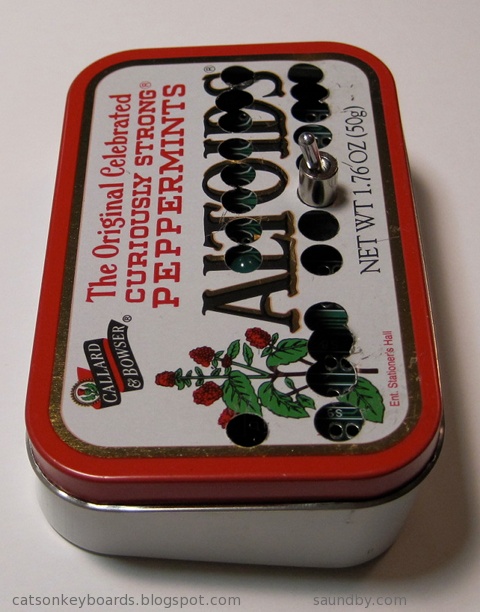
Here's what I got:
My first shot at engraving an IC top. It's not really an 8085 microprocessor, it's a dead ROM I happened to have hanging around.
The cut widths are about 35 thousandths. Too large for the level of detail in the smaller key pattern. The single large key above is scaled three times larger than the smaller keys. The base leg length for the small keys (the smallest segment size) is 25 thousandths. So it's easy to see why it didn't quite come out.
Still, the accuracy would have been plenty good, if I'd had a sharp enough bit.
Onward and upward! :)
Friday, April 22, 2011
8085 Microprocessor Reference Card Posted
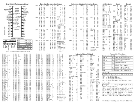
I put up a downloadable PDF of my own 8085 reference card on my website:
8085 Microprocessor Reference Card
I've added a bunch of information that I often use that's not on the original Intel reference card. This includes the undocumented 8085 instructions, timing for all instructions in T-States, a pinout and basic electrical reference, and a little more detail on the additional interrupts the 8085 adds to the 8080A design. Such as the fact that they're off by default, which I've forgotten at least a couple of times when writing test routines.
The card is laid out so that it can be printed on either a single-sided sheet or double sided to make two cards laid out with a front and back. The finished card looks great on a good cover stock paper, and folds to fit nicely into a pocket.
Wednesday, February 16, 2011
R.I.P. HFE Electronics, Sac's Electronic Part Source
I wrote a post about the HFE Electronics Store last year. They took over the former HSC Electronics store here in the Sacramento area. I drove by today, and the store was empty.

It looks like they went out of business two or three months ago, based on their Facebook discussion page. I only got down there four or five times a year, but I usually stocked up on parts, tools, and supplies on each trip.
Unfortunately this leaves me without a local storefront supplier for electronics. Our local Fry's Electronics carries enough in the way of components and such to make up for what Radio Shack dropped from their line a few years ago. But the selection of parts like interconnects, switches, and prototyping components they had at HFE was far greater than I'd expect to find anywhere other than an old-fashioned electronics store.
I do buy a lot of parts online now, I'll admit. I have about two shopping sprees a year for parts from places like The Electronic Goldmine and BG Micro. Not to mention frequent buys of parts from regular suppliers like Jameco, Mouser Electronics, All American Semiconductor.
But there's a difference.
At a local storefront, the parts are in my hands today. Plus, I can see them and handle them. With items like switches this is extremely important. I can also buy parts in small quantities speculatively then come back the next day if they work out and I need more (I've done this several times over the years at HFE/HSC. I remember once buying over $100 more in components on both days than I had planned on buying on each of two consecutive days. As I recall, the main culprit was some displays one the first day, and some uP support chips the second.)
Another thing that's important about local stores is their accessibility to youngsters getting into the electronics hobby. I know that for me when I was young, and now my daughters, fishing through boxes of parts and imagining what could be done with them is very inspirational. A couple of the fellows at the shop I haunted in my teens (Wenger's Electronics in Walnut Creek, CA) mentored me on several of my early projects. Plus there was advice I picked up from other customers. Not to mention that Wengers had a rack of bubble pack parts from Jameco, where I got my first 8080A.
A Long Time Since
I've been shopping at what was HSC and became HFE since I moved to the Sacramento almost exactly 25 years ago. Back then, I lived just a few blocks away. I not only stopped by in the evenings (if I had to run out in the evening for something, hey, HSC was next door to a Circle K store. How convenient is that? Pick up milk and potentiometers on the same trip out!) They had great flea markets on the weekends. You could pick up most of an Altair or IMSAI for a song back back then, enough that a little TLC would get you there (I wish I'd picked up an IMSAI for the front panel.)
There were other electronics stores* in Sac back then, plus I was right at the north end of town so it was easier to get to places like Natomas and Del Paso Heights for those stores. Since I moved to the foothills, HFE has been where I go.
This is where I met Dave Baldwin. I followed him home to get a treasure trove of old computer and parts he was seeking a home for. It's where I picked up about half of my test instruments, in various states of operability, that I use regularly today. It's where I've picked up interesting bits for many projects, and bits that still inhabit my parts drawers awaiting future fun projects.
I'll miss it.
----------------------------------------------------------------------------
Note: If you know something else in the area that I don't seem to know about (I already know about Fry's and Radio Shack, obviously), then drop a comment or an email, please!
*I'm using the term "electronics store" to refer to what I consider to be an electronics store, which is not a place that primarily sells consumer electronics. We used to call those "TV shops" or "Stereo Stores". I'm rather perturbed by such places moving in on the term "electronics store" (though many old-line electronics stores were once TV stores or repair shops.)
Tweet
HFE Electronics. A Valiant Effort, but Now It's Gone.
It looks like they went out of business two or three months ago, based on their Facebook discussion page. I only got down there four or five times a year, but I usually stocked up on parts, tools, and supplies on each trip.
Unfortunately this leaves me without a local storefront supplier for electronics. Our local Fry's Electronics carries enough in the way of components and such to make up for what Radio Shack dropped from their line a few years ago. But the selection of parts like interconnects, switches, and prototyping components they had at HFE was far greater than I'd expect to find anywhere other than an old-fashioned electronics store.
I do buy a lot of parts online now, I'll admit. I have about two shopping sprees a year for parts from places like The Electronic Goldmine and BG Micro. Not to mention frequent buys of parts from regular suppliers like Jameco, Mouser Electronics, All American Semiconductor.
But there's a difference.
At a local storefront, the parts are in my hands today. Plus, I can see them and handle them. With items like switches this is extremely important. I can also buy parts in small quantities speculatively then come back the next day if they work out and I need more (I've done this several times over the years at HFE/HSC. I remember once buying over $100 more in components on both days than I had planned on buying on each of two consecutive days. As I recall, the main culprit was some displays one the first day, and some uP support chips the second.)
Another thing that's important about local stores is their accessibility to youngsters getting into the electronics hobby. I know that for me when I was young, and now my daughters, fishing through boxes of parts and imagining what could be done with them is very inspirational. A couple of the fellows at the shop I haunted in my teens (Wenger's Electronics in Walnut Creek, CA) mentored me on several of my early projects. Plus there was advice I picked up from other customers. Not to mention that Wengers had a rack of bubble pack parts from Jameco, where I got my first 8080A.
A Long Time Since
I've been shopping at what was HSC and became HFE since I moved to the Sacramento almost exactly 25 years ago. Back then, I lived just a few blocks away. I not only stopped by in the evenings (if I had to run out in the evening for something, hey, HSC was next door to a Circle K store. How convenient is that? Pick up milk and potentiometers on the same trip out!) They had great flea markets on the weekends. You could pick up most of an Altair or IMSAI for a song back back then, enough that a little TLC would get you there (I wish I'd picked up an IMSAI for the front panel.)
There were other electronics stores* in Sac back then, plus I was right at the north end of town so it was easier to get to places like Natomas and Del Paso Heights for those stores. Since I moved to the foothills, HFE has been where I go.
This is where I met Dave Baldwin. I followed him home to get a treasure trove of old computer and parts he was seeking a home for. It's where I picked up about half of my test instruments, in various states of operability, that I use regularly today. It's where I've picked up interesting bits for many projects, and bits that still inhabit my parts drawers awaiting future fun projects.
I'll miss it.
----------------------------------------------------------------------------
Note: If you know something else in the area that I don't seem to know about (I already know about Fry's and Radio Shack, obviously), then drop a comment or an email, please!
*I'm using the term "electronics store" to refer to what I consider to be an electronics store, which is not a place that primarily sells consumer electronics. We used to call those "TV shops" or "Stereo Stores". I'm rather perturbed by such places moving in on the term "electronics store" (though many old-line electronics stores were once TV stores or repair shops.)
Monday, February 7, 2011
Coding Forms for Hand-Made Programs

I've posted some of the coding forms I use on my website.
For me, hand coding and hand assembling software is pleasant and relaxing. It's like crochet or embroidery (I do both of those as well as programming.) Something as simple as a printed form makes it nicer, neater, and faster.
The forms of my own I've posted are generic assembly language forms. I've also posted a TI 960/980 assembly language form as well as some programming forms for the HP-41C, HP-67 and HP-97 that I use with all of my programmable calculators (like my HP-35S.)
Friday, February 4, 2011
MAG-85: 8085 Microprocessor Project Software Progress
With the hardware work on my 8085 microprocessor trainer project about 99% complete, most of my effort over the past month or so has been developing a simple monitor program (a sort of mini-OS) for it.
The biggest part of that OS deals with the user interface (go figure), specifically the routines for controlling the LCD. The most demanding of the routines have been done for well over a year now, ever since I finished testing the LCD display with the breadboard version of the MAG-85.
When writing my own software while playing with the LCD (i.e. goofing off rather than writing code for the monitor), I've been writing lots of ad-hoc software to write to the LCD or control it whenever I wanted something more sophisticated than "write this character to the screen" or "send this string to the screen". Character out and string out routines were in my early test software. What I needed were things like automatic wrapping at the end of the displayed line and some terminal control commands.
Coding Rule: Make One to Throw Away
The display controller for the LCD has a larger "display" area than the LCD actually displays. Its buffer holds two lines of 40 characters. That's really nice on my other display which has a 40x2 LCD display on it. But the MAG-85 uses a 16x2 display. This means you can send characters to it, and it'll happily accept them and put them into the buffer in places that the LCD doesn't show. So you don't see over half of what you write. Or you need to keep track of how many characters you've written since the start of the line and wrap to the start of line 2 yourself. And so on.
In my first shot at a set of LCD routines for the system monitor, I wrote a bunch of stand alone cursor position tracking and movement routines. Then I had to invoke them from all over to keep track of stuff. And since the software had to do its own tracking, stuff would get missed, the LCD would get out of sync, and it became standard practice to re-home the cursor and display every so often to keep things from going off track for too long.
Plus the number of routines was getting out of hand, along with the size of the software. I'd intended the software to come in somewhere around a page in length, and I was at about twice that with only about half the software implemented! For comparison sake, a system that uses a hardware approach to display control (e.g. LED or other simple segmented displays with data buffers and select logic) rather than software like the LCD uses fits the whole monitor into about 1K of memory. I was looking at my LCD routines taking up as much room as the whole rest of the monitor.
Frankly, I felt that I was going the wrong way, and it slowed me down in getting the monitor done.
Coding Rule: Make Another to Keep
I decided to strip the code back to my original tight routines. All they do is initialize the LCD, send out a character or a command byte, or a string of characters. First, I dressed up my initialization routine by moving out some recurring code for delays into subroutines. This not only reduced the size of that routine, but made those subroutines available elsewhere.
Then I looked at my character out routine, and decided to put the intelligence about where the cursor was in there. After all, if it gets written this is where it happens. I built in an automatic wrap. It seemed to fit well, and it took a lot of heat off the user code. Suddenly things were looking a lot better.
Once I got to rewriting some of the other added functionality, it turned out smaller and simpler. It went so well, that I'm much farther along in implementing everything I want than I got with the old code. And at present I'm only just over a page in length, without having gone back to look for optimizations (repeated code and so on.) That'll come next, after which I'll be desk=checking my stack handling as I jump around between different routines.
But I'm much happier, and I've got a lot more to show for my time this time. It's nothing revolutionary, but there are times when it's a breakthrough just to step back and see the obvious.
Tweet
The biggest part of that OS deals with the user interface (go figure), specifically the routines for controlling the LCD. The most demanding of the routines have been done for well over a year now, ever since I finished testing the LCD display with the breadboard version of the MAG-85.
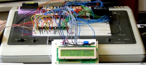
The Early MAG-85 with LCD Demo Program
When writing my own software while playing with the LCD (i.e. goofing off rather than writing code for the monitor), I've been writing lots of ad-hoc software to write to the LCD or control it whenever I wanted something more sophisticated than "write this character to the screen" or "send this string to the screen". Character out and string out routines were in my early test software. What I needed were things like automatic wrapping at the end of the displayed line and some terminal control commands.
Coding Rule: Make One to Throw Away
The display controller for the LCD has a larger "display" area than the LCD actually displays. Its buffer holds two lines of 40 characters. That's really nice on my other display which has a 40x2 LCD display on it. But the MAG-85 uses a 16x2 display. This means you can send characters to it, and it'll happily accept them and put them into the buffer in places that the LCD doesn't show. So you don't see over half of what you write. Or you need to keep track of how many characters you've written since the start of the line and wrap to the start of line 2 yourself. And so on.
In my first shot at a set of LCD routines for the system monitor, I wrote a bunch of stand alone cursor position tracking and movement routines. Then I had to invoke them from all over to keep track of stuff. And since the software had to do its own tracking, stuff would get missed, the LCD would get out of sync, and it became standard practice to re-home the cursor and display every so often to keep things from going off track for too long.
Plus the number of routines was getting out of hand, along with the size of the software. I'd intended the software to come in somewhere around a page in length, and I was at about twice that with only about half the software implemented! For comparison sake, a system that uses a hardware approach to display control (e.g. LED or other simple segmented displays with data buffers and select logic) rather than software like the LCD uses fits the whole monitor into about 1K of memory. I was looking at my LCD routines taking up as much room as the whole rest of the monitor.
Frankly, I felt that I was going the wrong way, and it slowed me down in getting the monitor done.
Coding Rule: Make Another to Keep
I decided to strip the code back to my original tight routines. All they do is initialize the LCD, send out a character or a command byte, or a string of characters. First, I dressed up my initialization routine by moving out some recurring code for delays into subroutines. This not only reduced the size of that routine, but made those subroutines available elsewhere.
Then I looked at my character out routine, and decided to put the intelligence about where the cursor was in there. After all, if it gets written this is where it happens. I built in an automatic wrap. It seemed to fit well, and it took a lot of heat off the user code. Suddenly things were looking a lot better.
Once I got to rewriting some of the other added functionality, it turned out smaller and simpler. It went so well, that I'm much farther along in implementing everything I want than I got with the old code. And at present I'm only just over a page in length, without having gone back to look for optimizations (repeated code and so on.) That'll come next, after which I'll be desk=checking my stack handling as I jump around between different routines.
But I'm much happier, and I've got a lot more to show for my time this time. It's nothing revolutionary, but there are times when it's a breakthrough just to step back and see the obvious.
Saturday, December 4, 2010
Retrocomputing for the Holidays
What could be better than an old computer under the Christmas tree? It's a fun, inexpensive gift. There's always something old under out Christmas tree. Among the larger items have been the Commodore 64 that I gave my daughters as their first computer ten years ago. It included a monitor and floppy drive, of course, and copies of the user's manual and programmer's guide.
They'd both already started programming in BASIC on my Apple IIe during the prior year. So they were ready for the C-64! I got myself a Softcard for my Apple IIe that same year.
Two years later, I added a Plus/4, since they were frustrated with the lack of direct graphics commands on the C-64. Peek and poke wasn't good enough. ;) That same year some friends gave me their Laser 128 (Apple IIc clone.)
Christmas Cheer with PA-RISC
Another two years pass, and they both got an HP9000/700 series Unix workstation. They spent Christmas break learning Bourne shell and playing with Neko under X-Windows. Yeah, these weren't 8-bitters, but they were fun old systems that ran plenty of network apps. I had a MUD on my Unix workstation, and they learned how to telnet in and play pretty quickly. Their typing improved dramatically.
I picked up an Amiga 500 and that became the family's Christmas present the next year. We hooked it up to our 36" TV and played music, games, and a bunch of demos.
The year after that, a friend gave me a Bigboard I system. CP/M, 64K, and two big 8" floppy drives. Wordstar and BASIC-80 heaven. Everyone gathered around to roast chestnuts over the power supply and listen to the disk drives churn. ;)
Sure, it's got iTunes. Does it do X-Windows?
That same year, my daughters got upgraded to Macs, G3 B&Ws. They were excited about getting a computer that would run iTunes, but first they made sure that all their Unix stuff would run as well. Once they were sure they weren't giving up the Unix command line and could port their applications, THEN they were OK with the upgrade.
Three years ago, I did some repairs to a Kaypro 4 to get it working again. Unfortunately I haven't figured out how to read and write standard diskettes with it yet. It's a souped-up unit, with an aftermarket ROM, hard disk, and floppy drives that include both double and high density units. It got set on the back burner in favor of some other projects, once they're finished I'll get back to determining if I've got all the right software to go with the ROM that's in the system.
Visiting Old Friends
Two years ago, I actually avoided adding any new hardware for the year. Instead, I spent time during the holidays pulling out several of the systems I have that have been a bit neglected and giving them some TLC then playing with them. The Apple IIe, my own C-64, another Plus/4, and the Big Board.
Last year was the year of hardware projects. I had a new 8085 computer on a breadboard (see the story at http://saundby.com/), and was preparing to move it to soldered circuit cards. I was also migrating my Ampro Little Board (a Z-80 system) from loose components on the table top to living in a box like a proper computer.
Bringing Up the Ampro Little Board
Catching Up for Christmas
This year I'm working to finish the non-breadboarded version of my 8085 and building up a Membership Card (1802-based computer, similar to a COSMAC Elf from 1976 but a lot smaller) in a decorative little Victorian-style case. I'll be posting that on my web page at saundby.com soon, I expect.
I'm keeping my eyes peeled for a Commodore 128 at the thrift stores, too. That'd really round out this Christmas year.
What's on Your List?
What retrocomputer experiences have you had for Christmases past, and what are you hoping for under the tree this year that's hopelessly "out of date"? :)
Tweet
They'd both already started programming in BASIC on my Apple IIe during the prior year. So they were ready for the C-64! I got myself a Softcard for my Apple IIe that same year.
Two years later, I added a Plus/4, since they were frustrated with the lack of direct graphics commands on the C-64. Peek and poke wasn't good enough. ;) That same year some friends gave me their Laser 128 (Apple IIc clone.)
Christmas Cheer with PA-RISC
Another two years pass, and they both got an HP9000/700 series Unix workstation. They spent Christmas break learning Bourne shell and playing with Neko under X-Windows. Yeah, these weren't 8-bitters, but they were fun old systems that ran plenty of network apps. I had a MUD on my Unix workstation, and they learned how to telnet in and play pretty quickly. Their typing improved dramatically.
I picked up an Amiga 500 and that became the family's Christmas present the next year. We hooked it up to our 36" TV and played music, games, and a bunch of demos.
The year after that, a friend gave me a Bigboard I system. CP/M, 64K, and two big 8" floppy drives. Wordstar and BASIC-80 heaven. Everyone gathered around to roast chestnuts over the power supply and listen to the disk drives churn. ;)
Sure, it's got iTunes. Does it do X-Windows?
That same year, my daughters got upgraded to Macs, G3 B&Ws. They were excited about getting a computer that would run iTunes, but first they made sure that all their Unix stuff would run as well. Once they were sure they weren't giving up the Unix command line and could port their applications, THEN they were OK with the upgrade.
Three years ago, I did some repairs to a Kaypro 4 to get it working again. Unfortunately I haven't figured out how to read and write standard diskettes with it yet. It's a souped-up unit, with an aftermarket ROM, hard disk, and floppy drives that include both double and high density units. It got set on the back burner in favor of some other projects, once they're finished I'll get back to determining if I've got all the right software to go with the ROM that's in the system.
Visiting Old Friends
Two years ago, I actually avoided adding any new hardware for the year. Instead, I spent time during the holidays pulling out several of the systems I have that have been a bit neglected and giving them some TLC then playing with them. The Apple IIe, my own C-64, another Plus/4, and the Big Board.
Last year was the year of hardware projects. I had a new 8085 computer on a breadboard (see the story at http://saundby.com/), and was preparing to move it to soldered circuit cards. I was also migrating my Ampro Little Board (a Z-80 system) from loose components on the table top to living in a box like a proper computer.
Bringing Up the Ampro Little Board
Catching Up for Christmas
This year I'm working to finish the non-breadboarded version of my 8085 and building up a Membership Card (1802-based computer, similar to a COSMAC Elf from 1976 but a lot smaller) in a decorative little Victorian-style case. I'll be posting that on my web page at saundby.com soon, I expect.
I'm keeping my eyes peeled for a Commodore 128 at the thrift stores, too. That'd really round out this Christmas year.
What's on Your List?
What retrocomputer experiences have you had for Christmases past, and what are you hoping for under the tree this year that's hopelessly "out of date"? :)
Saturday, September 18, 2010
8085 Disaster! (well, a minor setback, but I'm not happy about it.)
I'm in the final stages of assembling the permanent hand-wired version of my 8085 project, and I've run into a problem.
3 Switches Become 1 Big Problem
There are three critical switch inputs to the 8085 on the front panel. They are the TRAP, RST5.5 and RST7.5 signals to the 8085. Essentially, each tells the 8085, "Stop what you're doing and do this instead."
It Worked Fine on the Test Bench!
When I built this project on solderless breadboard I didn't have any serious space limitations, so I did full "debouncing" on each switch, to prevent electrical noise caused by the switch from sending a whole bunch of "stop what you're doing!" messages all in a row when the user just presses the switch once.
On the soldered-up permanent version, I decided to save a little bit of space on the circuit board by trying to debounce on the cheap. A normal debounce circuit uses two inverters to clean up the electrical noise. I had a chip on the board that had six inverters in it, two of which were in use. That left me four inverters, for three signals. I needed six to do the job right.
Too Clever by Half
But, I had a "clever" idea. I thought I'd see if I could get by with a circuit that only uses one gate per signal. Not a full debounce, but a circuit called a "Schmitt Trigger." I built it up and tested it on the solderless breadboard.
It worked just great!
Then I built it up on the soldered board. It worked great there, too.
Then I went and bought some prettier switches to use on my new system's box. It worked pretty well. It seemed OK...
Then I did a test fit on the box with all the parts. I pressed my pretty new switches.
Disaster!
When I was pressing the new switches on a handheld box, rather than against a tabletop, I got a whole bunch of signals sent to the 8085 for each time I pressed the switch. The results were pretty ugly.
A Quick Fix is No Fix
I tried out some quick-fixes, as well as making sure all my connections were good. I'd hate to redesign and modify the circuit only to find out the problem was a loose connector all along. The connectors were tight, and the quick fixes helped a bit, but didn't fix the problem. The original (ugly) switches I used worked fine, but I tried a selection of switches in the circuit and most of them had the same problem when hand-held even when they didn't have any problems on the test bench. (I really did test the snot out of this when I first went with the shortcut. But I didn't get all the conditions right for a good enough test. Now I'm paying the price.)
I considered changing out the switches. But this would be a bit of a cop-out. I want to make this something someone else can build and enjoy without having to go through the tweaking and testing and all that I'm doing as I build it. I want others to be able to build it and just have it work, so long as all the bits are in the right places. I can't guarantee that everyone who decides to build it is going to get "clean" switches. So I have to go back and change the design to use real debounce. Then test that, under adverse conditions, like with a rusty knife switch.
One of the quick fixes I tried would probably have been good enough to work under most conditions with a software change that would have delayed any action on the switch input for a fraction of a second. I could have gone with that, and felt sorta pretty good about it. Except that there's a fairly likely condition that that wouldn't cover.
The Deadly Condition
If the user presses the switch, and holds it down for a bit before releasing it, there'll be a second switch event on the release. If someone has a habit of sort of "leaning on" the switches then this will occur to them fairly frequently, and probably ruin their experience using the computer.
I did say these switches are important--in the OS I use them for a warm reset, and vectoring to the user's program. The third one is left for the user in their own programs. But if those functions aren't reliable, it sorta hoses the whole affair. So it's time for me to do the right thing.
Test, Test, Retest, Pray and You Shall Receive
Tomorrow I expect to be protoboarding the correct circuit that I probably should have done in the first place. I'll test it, and if I'm not 100% convinced, I'll use a different sort of circuit, called a "one-shot" or monostable, and make darn well sure with belt and suspenders and a rope tied to a thick tree limb. I may try to avoid adding another IC to the board by using transistors for the last two inverters, or I may try to keep down the varieties of components I use by just dropping in another 4049 in addition to the one there now. On my other part choices I've opted to keep the number of different parts low by reusing the same chips over and over wherever possible.
I'm expecting to put in another 4049, even though it ties up more board space than I like. I might get creative about where I put it, but then again I may not.
Finally, Fitting It In
It's not like I don't have open board space. But I had plans for that space in the future. A memory bank select, another memory IC, and an RS-232 chip. I think the space saved for the RS-232 chip is going to get used. Besides, I may be able to fit in a little Dallas/Maxim chip in one of the odd corners later, or just "float" it on a daughterboard connected to the RS-232 connector.
After all, the core computer has to be working before I start worrying about expansions.
Tweet
3 Switches Become 1 Big Problem
There are three critical switch inputs to the 8085 on the front panel. They are the TRAP, RST5.5 and RST7.5 signals to the 8085. Essentially, each tells the 8085, "Stop what you're doing and do this instead."
It Worked Fine on the Test Bench!
When I built this project on solderless breadboard I didn't have any serious space limitations, so I did full "debouncing" on each switch, to prevent electrical noise caused by the switch from sending a whole bunch of "stop what you're doing!" messages all in a row when the user just presses the switch once.
On the soldered-up permanent version, I decided to save a little bit of space on the circuit board by trying to debounce on the cheap. A normal debounce circuit uses two inverters to clean up the electrical noise. I had a chip on the board that had six inverters in it, two of which were in use. That left me four inverters, for three signals. I needed six to do the job right.
Too Clever by Half
But, I had a "clever" idea. I thought I'd see if I could get by with a circuit that only uses one gate per signal. Not a full debounce, but a circuit called a "Schmitt Trigger." I built it up and tested it on the solderless breadboard.
It worked just great!
Then I built it up on the soldered board. It worked great there, too.
Then I went and bought some prettier switches to use on my new system's box. It worked pretty well. It seemed OK...
Then I did a test fit on the box with all the parts. I pressed my pretty new switches.
Disaster!
When I was pressing the new switches on a handheld box, rather than against a tabletop, I got a whole bunch of signals sent to the 8085 for each time I pressed the switch. The results were pretty ugly.
A Quick Fix is No Fix
I tried out some quick-fixes, as well as making sure all my connections were good. I'd hate to redesign and modify the circuit only to find out the problem was a loose connector all along. The connectors were tight, and the quick fixes helped a bit, but didn't fix the problem. The original (ugly) switches I used worked fine, but I tried a selection of switches in the circuit and most of them had the same problem when hand-held even when they didn't have any problems on the test bench. (I really did test the snot out of this when I first went with the shortcut. But I didn't get all the conditions right for a good enough test. Now I'm paying the price.)
I considered changing out the switches. But this would be a bit of a cop-out. I want to make this something someone else can build and enjoy without having to go through the tweaking and testing and all that I'm doing as I build it. I want others to be able to build it and just have it work, so long as all the bits are in the right places. I can't guarantee that everyone who decides to build it is going to get "clean" switches. So I have to go back and change the design to use real debounce. Then test that, under adverse conditions, like with a rusty knife switch.
One of the quick fixes I tried would probably have been good enough to work under most conditions with a software change that would have delayed any action on the switch input for a fraction of a second. I could have gone with that, and felt sorta pretty good about it. Except that there's a fairly likely condition that that wouldn't cover.
The Deadly Condition
If the user presses the switch, and holds it down for a bit before releasing it, there'll be a second switch event on the release. If someone has a habit of sort of "leaning on" the switches then this will occur to them fairly frequently, and probably ruin their experience using the computer.
I did say these switches are important--in the OS I use them for a warm reset, and vectoring to the user's program. The third one is left for the user in their own programs. But if those functions aren't reliable, it sorta hoses the whole affair. So it's time for me to do the right thing.
Test, Test, Retest, Pray and You Shall Receive
Tomorrow I expect to be protoboarding the correct circuit that I probably should have done in the first place. I'll test it, and if I'm not 100% convinced, I'll use a different sort of circuit, called a "one-shot" or monostable, and make darn well sure with belt and suspenders and a rope tied to a thick tree limb. I may try to avoid adding another IC to the board by using transistors for the last two inverters, or I may try to keep down the varieties of components I use by just dropping in another 4049 in addition to the one there now. On my other part choices I've opted to keep the number of different parts low by reusing the same chips over and over wherever possible.
I'm expecting to put in another 4049, even though it ties up more board space than I like. I might get creative about where I put it, but then again I may not.
Finally, Fitting It In
It's not like I don't have open board space. But I had plans for that space in the future. A memory bank select, another memory IC, and an RS-232 chip. I think the space saved for the RS-232 chip is going to get used. Besides, I may be able to fit in a little Dallas/Maxim chip in one of the odd corners later, or just "float" it on a daughterboard connected to the RS-232 connector.
After all, the core computer has to be working before I start worrying about expansions.
Tuesday, September 14, 2010
8085 Computer Power Management
I'm in the final stages of hardware work on my 8085 computer project. Today I spent some time working on reducing how much power it uses.

With all peripherals turned on at full power, some of them at a higher level than would be normal or reasonable, the whole thing pulled 720mA at 5V. At full reasonable power levels, everything on, it came down to about 250mA. I put in current limiting to cap it at that level.
Then I went hunting for further power savings. The plan is to run this thing off of batteries in the not too distant future (I normally run it off an AC adapter now.) By seeing how little power I could feed to the LEDs in the system while still having them visible in bright light, I was able to cut overall power use down to about 160mA with everything on. It draws about 125mA with the LCD display on, the system running full bore, but no extra outputs pulling current. I can live with that.
What surprised me the most was that changing the CPU from an 8085AH microprocessor to an 80C85 (CMOS, low power version) didn't make any significant difference to the amount of power the system required. The LEDs accounted for almost all of the decrease from 720mA to 125mA.

I'm very close to closing this box up and calling it done. At least until I open it up for further upgrades. Upgrades like full 64K memory decode, an additional 8K of memory on board, and an RS-232 serial port. Later.
Tweet
The MAG-85 still looks like a rats nest here. I pulled out a bunch of parts for today's testing. It'll go back together again even better.
With all peripherals turned on at full power, some of them at a higher level than would be normal or reasonable, the whole thing pulled 720mA at 5V. At full reasonable power levels, everything on, it came down to about 250mA. I put in current limiting to cap it at that level.
Then I went hunting for further power savings. The plan is to run this thing off of batteries in the not too distant future (I normally run it off an AC adapter now.) By seeing how little power I could feed to the LEDs in the system while still having them visible in bright light, I was able to cut overall power use down to about 160mA with everything on. It draws about 125mA with the LCD display on, the system running full bore, but no extra outputs pulling current. I can live with that.
What surprised me the most was that changing the CPU from an 8085AH microprocessor to an 80C85 (CMOS, low power version) didn't make any significant difference to the amount of power the system required. The LEDs accounted for almost all of the decrease from 720mA to 125mA.
The enclosure during inspection by Quality Control. The first attempt is on the left, the final version on the right.
I'm very close to closing this box up and calling it done. At least until I open it up for further upgrades. Upgrades like full 64K memory decode, an additional 8K of memory on board, and an RS-232 serial port. Later.
Wednesday, June 30, 2010
Retrocomputing Summer
Aside from some astronomy, I've been spending a lot of my free time this summer on some retrocomputing projects. In particular, I've been working on my homebrew 8085 single board computer and my Ampro Little Board Plus Z-80 systems. Alongside that, I've been trying to fit a new computer that's similar to a COSMAC Elf into an Altoids tin.

Retrocomputing in Your Pocket.
Meanwhile, I'm trying to fit my Membership Card into its tin. I think my switches are too tall, so I'm going to have to make some other accomodations.

Each step of the project adds just one to three new pieces to the computer. The complete computer is only twelve integrated circuits, plus resistors, capacitors, and other small parts. It can be built with only eight ICs, if you want a simpler version that gives up a couple of extras. These can always be added in later, if desired. The real key to the project is that it provides a complete, functional 8085 system similar to the SDK-85 development system that can be built up from simple parts that are easy to understand and use in programs.
Most of my work lately, other than playing with software and deciding how I want the programmer's interface to work in its operating system, has been on the front panel of the computer and its enclosure. I want it to be something that someone with minimal tools, and even without power tools, can build from common materials available at an ordinary hardware store. I also want it to be attractive enough to show off after it's built, not something that looks like it belongs in a junkpile.

Since posting details on the 8085 construction project takes about 3 times as long as doing it, I've been holding off on doing an update of the project on its site until I have the enclosure complete. Now I'm almost done, so an update will probably occupy the later part of my summer.

I got a pair of system boards for these from Dave Baldwin when he was cleaning out some old computers prior to a move. One night, I really wanted to get one of the many systems up and running that Dave had given me, and since these seemed like they'd be the easiest to get running I grabbed one and got it going.


Then Vic Maris of StellarVue Telescopes offered me an old desk he didn't need at his offices any more. He said it was large. It is. I had to do some major work to get it into my office. But once there, I put my usual computers on it (an iMac 20" and a Beige G3 PowerPC Mac), and had enough room for one more computer!

I put the Ampro's current box (a PC's beige box) under the desk. I've got another enclosure for it that'll be much more attractive and interesting--but that's another project yet to come. On top, I had plenty of room for my ADDS 2020 terminal, which is the user interface for the Ampro. Unlike the original Big Board computer (the "Ferguson"), the Ampro uses a terminal, whereas the Big Board has a built in CRT and keyboard interface.
Once I got everything in place, I started working with my ADDS terminal to try to get the best image out of it. I originally used this terminal with the Ampro because it's the smallest full terminal I've got. I took a look at all the space on my new desk, and realized...I could use a better terminal. So I pulled out my VT-102, which has a very nice white on black character display and is very sharp.

The VT-102 wasn't perfect, though. So, thanks to some help from fellow retrocomputerists I was able to find the technical info I needed to adjust the character height on the display (it was a little taller in one part than another when it came out of the garage.) Now it's perfect.
Now I'm happily writing games in Turbo Pascal at my desk, and the space next to my easy chair is waiting for another project to move in while my wife's back is turned.

Since this picture was taken I've cleaned up. Really.
The breadboard version of my 8085 computer, the MAG-85 is still in use, by the way. That's where I've been doing my OS development while I finish the permanent version of the hardware. That way I don't have to worry if I've got the permanent one's keyboard and display off for work on the face panel if I want to sit down and code some 8080/8085 assembly.
Lee Hart's 1802-Based Mini-Microcomputer: The Membership Card.
Retrocomputing in Your Pocket.
Lee Hart's Membership Card computer. It's based on the RCA 1802 microprocessor, and it's a close cousin to the COSMAC Elf computer (Google it, if you don't know about it!)
Meanwhile, I'm trying to fit my Membership Card into its tin. I think my switches are too tall, so I'm going to have to make some other accomodations.
The tin doesn't quite close up. My interconnect between the PCBs may be too tall, or my switches aren't laying as low as Lee's did. It's only about 1.5mm, but it's enough. I'm working on Plan B now.
My 8085 Handheld Single Board Computer Project
My first shot at a front panel layout for my 8085 computer, laid out on acrylic sheet to make it easy to see what's where.
Each step of the project adds just one to three new pieces to the computer. The complete computer is only twelve integrated circuits, plus resistors, capacitors, and other small parts. It can be built with only eight ICs, if you want a simpler version that gives up a couple of extras. These can always be added in later, if desired. The real key to the project is that it provides a complete, functional 8085 system similar to the SDK-85 development system that can be built up from simple parts that are easy to understand and use in programs.
Most of my work lately, other than playing with software and deciding how I want the programmer's interface to work in its operating system, has been on the front panel of the computer and its enclosure. I want it to be something that someone with minimal tools, and even without power tools, can build from common materials available at an ordinary hardware store. I also want it to be attractive enough to show off after it's built, not something that looks like it belongs in a junkpile.
The partially-complete Masonite face panel of my 8085 computer.
Since posting details on the 8085 construction project takes about 3 times as long as doing it, I've been holding off on doing an update of the project on its site until I have the enclosure complete. Now I'm almost done, so an update will probably occupy the later part of my summer.
Ampro Little Board Plus Z-80
My Ampro Little Board Plus, in its original incarnation. A pile of parts on a kitchen table.
I got a pair of system boards for these from Dave Baldwin when he was cleaning out some old computers prior to a move. One night, I really wanted to get one of the many systems up and running that Dave had given me, and since these seemed like they'd be the easiest to get running I grabbed one and got it going.
A complete computer, with Z-80 CPU at 4MHz, Floppy Disk Drive Controller, Serial and Parallel I/O, and SCSI all on one small card--in 1984!
Honey, how about we eat dinner on the patio tonight?
Then Vic Maris of StellarVue Telescopes offered me an old desk he didn't need at his offices any more. He said it was large. It is. I had to do some major work to get it into my office. But once there, I put my usual computers on it (an iMac 20" and a Beige G3 PowerPC Mac), and had enough room for one more computer!
My new desk, with Three full size computers.
I put the Ampro's current box (a PC's beige box) under the desk. I've got another enclosure for it that'll be much more attractive and interesting--but that's another project yet to come. On top, I had plenty of room for my ADDS 2020 terminal, which is the user interface for the Ampro. Unlike the original Big Board computer (the "Ferguson"), the Ampro uses a terminal, whereas the Big Board has a built in CRT and keyboard interface.
Once I got everything in place, I started working with my ADDS terminal to try to get the best image out of it. I originally used this terminal with the Ampro because it's the smallest full terminal I've got. I took a look at all the space on my new desk, and realized...I could use a better terminal. So I pulled out my VT-102, which has a very nice white on black character display and is very sharp.
The Beige G3 runs Lemmings and Warcraft, the iMac is my interwebs machine, it's desktop background is an image of the Big Board computer PCB, and to the right is my Ampro's terminal, here showing the utilities menu.
The VT-102 wasn't perfect, though. So, thanks to some help from fellow retrocomputerists I was able to find the technical info I needed to adjust the character height on the display (it was a little taller in one part than another when it came out of the garage.) Now it's perfect.
Now I'm happily writing games in Turbo Pascal at my desk, and the space next to my easy chair is waiting for another project to move in while my wife's back is turned.
Getting the new desk in meant moving some stuff out.
Since this picture was taken I've cleaned up. Really.
The breadboard version of my 8085 computer, the MAG-85 is still in use, by the way. That's where I've been doing my OS development while I finish the permanent version of the hardware. That way I don't have to worry if I've got the permanent one's keyboard and display off for work on the face panel if I want to sit down and code some 8080/8085 assembly.
Wednesday, March 31, 2010
HFE: Sacramento Area Electronics Parts Source
There's a neat little place in Sacramento--next door to North Highlands--that sells lots of electronics supplies and surplus stuff, as well as some consignments. It's called HFE Electronics. It's at the prior location of HSC (Halted Specialties Corp., better known as HSC Electronic Supply.) HSC decided to consolidate, pulling out of the Sacramento location after over 25 years and focusing their attention on their Bay Area store and online sales.

HFE fills the gap that would have been left with the loss of HSC in this area. Not only that, but they've picked up for the Popkey Electronics store that recently closed here. They bought out Popkey's stock and are integrating it into their inventory now.
HFE is a fun place to poke around, ask questions of the staff (or, in my case, I more often get involved in helping the staff answer questions from other customers) and otherwise pick up all sorts of fun bits of electronics. They have everything from discrete components to ICs to equipment. There's new retail stuff as well as heaps of surplus and used stuff. There's lots of bits and bobs for those of us who like playing with microcontrollers, those of us who like building up analog circuits from scratch, amateur radio people, digital electronics types, tinkerers with pre-existing equipment, repairers of the $100 item with a broken ten cent part, and so on. Count me in all the above categories. I seldom get out the door without being about $100 lighter. :)
Among the things I noticed my last time in (no guarantees this will all be there when you walk in, especially if I beat you there) are:
- An Odyssey 2 game console from the 70s (based on the 8048 CPU, with lots of room inside the case for mods!
- Some Tek scopes and modules
- An old Mac SE/30 unit (sans keyboard and mouse.)
- Lots of interesting rocker switches
- A bunch of LCD displays with 44780 controllers and similar
- Oodles of LEDs and displays (I've picked up a bunch of dual digit 14 segment displays, among others.)
- Prototyping boards, tools, wire jumpers for solderless breadboards, and other proto stuff.
- Interconnects and sockets of all sorts of varieties.
Monday, March 29, 2010
8085 Project Schematic Posted
I've posted a schematic for my 8085 based single board computer, the MAG-85, on my web site. The schematic covers the entire main board, previously I had only posted schematics of parts of the system in the assembly instructions.
Click the image to go there. The schematic is linked under "References" at the bottom of the page.

I'm presently completing the parts of the schematic that cover the front panel components as well as the bill of materials. This will all be posted as a PDF once it is complete.
In hardware, I have finished the keyboard and am assembling the front panel and the enclosure. This is all turning out very nicely, I'll be posting pictures soon. I'm especially happy with how the keyboard turned out. It looks really spiffy, even though it was created using very low-tech methods (I'm working to keep the whole project at a garage and desktop tech level for construction.)
Click the image to go there. The schematic is linked under "References" at the bottom of the page.
I'm presently completing the parts of the schematic that cover the front panel components as well as the bill of materials. This will all be posted as a PDF once it is complete.
In hardware, I have finished the keyboard and am assembling the front panel and the enclosure. This is all turning out very nicely, I'll be posting pictures soon. I'm especially happy with how the keyboard turned out. It looks really spiffy, even though it was created using very low-tech methods (I'm working to keep the whole project at a garage and desktop tech level for construction.)
Thursday, March 18, 2010
8085 Microprocessor Project: MAG-85
Here's a picture of the completed hand-wired circuit board for the MAG-85 (Micro Applications Gadget) 8085-based microcomputer system:

More info on this project at saundby.com.
I'm presently working on both a permanent front panel/enclosure and the permanent software. I'll be writing a machine language monitor program that will provide a number of utility routines for using the system's I/O.
The system has a 4x5 keypad,and an LCD display (16x2 is used here, I'll write the software to allow any two-line display from 16x2 to 40x2.) It also has 16 extra digital inputs and outputs. In the image eight of each are in use to read the state of a bank of DIP switches and display that on the 8 LEDs. The system can be expanded off-board with up to an additional 40 additional I/Os with the present I/O decoders.
The 8085's interrupt inputs are available as well, above I have switches on TRAP (the 8085's non-maskable interrupt) and RST7.5. RST6.5 is used by the keyboard, and RST5.5 will also be available on the front panel as a user program vector switch.
Everything's coming together nicely on this project now. I have detailed instructions on constructing the circuit on the project web page, with detailed instructions for a hand-wired board like the one above soon to come.
Tuesday, November 24, 2009
8085 Permanent Hardware Free Run Test

Free Run Mode on the MAG-85 Trainer Under Construction
Above is the permanent version of the 8085 trainer I'm building up. I did a "free-run" test with it today, you can see it wired up for that in the image above.
You can read about how to build your own on my 8085 Trainer Project Page on my website.
What you're seeing above is a prototyping printed circuit board with the beginnings of a microcomputer system built up on it. For this test it's got some components on a small solderless breadboard, which is temporarily held on the printed circuit board with a rubber band. The permanent hardware on the board starts at the upper left, where the power supply resides above the shiny metal can. The shiny metal can is the crystal oscillator, which provides the basis of the clock for the 8085 microprocessor. Beneath that is a 4049 chip, which has six inverters in it. Two of these are used for this test, for the 8085's clock, and their output is on the blue wires that go from the 4049 to the big chip, which is the 8085 microprocessor.
In the "free-run" test, the 8085 is tricked into thinking its entire memory is filled with zeros, which translates into "No Operation" or NOP instructions. This makes the 8085 step through its entire memory space. The top four memory address lines of the 8085 are hooked up to LEDs, which blink as the 8085 goes through its memory space. They blink in a pattern that makes it easy to see that the 8085 is doing what it's supposed to do.
The permanent version of this circuit is being built up in the same way I built up the prototype, except that I had to build up a power supply, and of course the permanent version is soldered rather than solderless (except for the temporary test components, as you see in the image.)
Whew!
It's very nice to get to this point and have everything work. When you don't have a custom-made printed circuit board, it's very easy for a lot of things to go wrong. Now I know that my power supply and clock circuits are good, and that I've got the basic wiring for the CPU correct. I've had projects like this crash and burn in the past because I jump in and wire up everything, rather than going forward a bit at a time, testing each section as its added. Even in cases where all the wiring rings out good, and there's no obvious problems when testing before installing the chips in the sockets, I've had small systems refuse to run or refuse to run reliably when assembled.
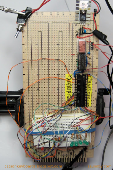
The circuit is checked out step by step before the 8085 CPU is inserted by probing the 8085's pin positions to make sure the correct voltages and signals are in place.
Now I do things one piece at a time and deal with the fact that getting a working system means spending twice as long in assembly and test as plunging forward headlong and hoping for the best.
For example, in these pictures you can see the guides I put on tape for the pins of the 8085. This makes it a lot easier for me to get the wires in the right places. I also have the 4049 on a little jig to tie its unused inputs to ground until I'm ready to use them. This takes extra time, but lets me isolate different sections of the circuit as I build them, rather than having to build up the whole computer as a piece in order to keep the extra inputs from floating, and potentially causing trouble.
Besides, the build-up and testing is part of the fun of a project like this. No point in rushing past part of the fun. Making something like this is like a crafts project. If you don't enjoy needlework, you're better off buying finished works rather than making your own. The same goes with microcomputer systems.
Other posts on the 8085 Trainer I'm building:
8085 Project Update
8085 Prototype Hardware Complete
8085 Trainer Project
8080A CPUs from NTE (illustration of 8085 Free Run Circuit)
8085 SDK-85 Homebrew Style
Also see:
The MAG-85 Trainer Project Site
Wednesday, November 11, 2009
8085 Project Update
I'm still working on my 8085-based SBC. I've finished the power supply for the permanent hard-wired one since completing the breadboard version. I've been slowed a bit by a couple of items--I've been trying to find a way of doing schematics that I'm happy with, and I had a minor medical procedure that's had complications putting me in enough pain that i'm having trouble concentrating for long periods of time.
The pain is just pain of the useless variety--there's nothing wrong that it's signalling. But it's cut into my productivity and the number of hours I'm able to do things that require thought and precision each day. As a result I'm getting less time in on the 8085 than I am on Mythbusters DVDs in the evening. As things get better (slowly), I'm really looking forward to knocking the 8085 hardware out. If all goes well, I should be able to get the core system in this weekend--clock oscillator, CPU, address latch, and memory. Plus an LED on SOD for testing. That'll have a connector since the final version will have the LED on a user interface board mounte on the enclosure.
I've managed to put together the material for the web pages on adding and testing the keyboard as well. Next update to the project pages at saundby.com will include that. It's much more fun with a keyboard.
Developing the system monitor will start once the permanent hardware is complete (scheduled to be around Thanksgiving to clear the decks for another hardware project.) I expect software development of the initial version of the system monitor to run into January. Updates will continue indefinitely... ;)
Tuesday, October 13, 2009
8085 Hardware Prototype Complete
I've finished the breadboard hardware prototype for my 8085 Trainer. Now I've started work on the permanent hardware. I've got what I think is a pretty good idea for the enclosure, which should be easy to construct from standard hardware store stuff. The full story on that will come on my web site once I get it done.
For today, I've added more of the hardware construction info: Adding Interrupts to the LCD Code. This is the last step in construction before adding the keyboard. The keyboard controller uses an interrupt to let the 8085 know it's got a keystroke ready for reading. So putting interrupt handlers in the LCD code prepare the system for showing keystrokes on the display. Once the code is entered as given, the keyboard hardware can be installed and tested with no further software changes.
As soon as I finish this post, I'll be working on the web pages for putting in the keyboard hardware. The MAG-85 uses a 4x5 matrix keypad in addition to the hardware switches. The keypad will be a hexadecimal keypad and some soft switches for controlling the entry modes. Hard switches will be used for system reset, memory protection, single stepping, and other functions. I'm still working out the details for the final system monitor software.
Now, back to web page editing. I must get the web pages up to date, or I don't get to go back to playing with the hardware.
Monday, September 28, 2009
8085 Trainer Project
I've posted a web page on my 8085 micro trainer that I'm building. I've posted instructions on building the system up just as I'm building it, along with my notes.
To date, I've posted instructions that go through getting the core system running with a memory, adding switch inputs through interrupts, and giving the 8085 an LCD display as an output. I'm presently integrating the LCD driver code with the interrupt code, then I'll add a keyboard to the system.
This system will be a small, hand-held micro trainer. It's intended for easy, anywhere machine language programming of an 8080-compatible system, for those of us who find such activities fun and relaxing.
Check it out >>
Yes, I do machine language programming for relaxation. I also crochet Irish lace and embroider knotwork patterns for relaxation. I like things that are mentally engaging, but that can proceed at a casual pace for unwinding at the end of the day.
In case I'm really fried at the end of the day, I keep databooks stacked on my bedside stand.
Have a look at my electronics web pages.
Monday, September 21, 2009
8080A CPUs from NTE
I was in Fry's Electronics recently looking for some parts. I didn't find what I was looking for (non-volatile RAMs) but while I was looking I went through the catalog of parts they carry--the NTE semiconductor catalog.
You could have colored me shocked when I saw the 8080A and its support chips in that catalog! I looked around to make sure I hadn't slipped back 30 years to the Fry's grocery store with the "chips" aisle: potato chips on one side, semiconductors on the other.
What surprised me even more was that while the 8080A was there, the 8085 wasn't.

Once you add a clock chip and control signal demux chip you're talking real money, especially today when a solid microcontroller comes in at a buck or less.
The real mystery to me is where these chips are being made. Is there some fab out there still cranking out 70's-era NMOS process wafers? On 2 or 3 inch? Or are these old production stockpiles? Or--heavens forbid--did someone bring the 8080A to a new process? Five-metal sub-micron 8080As, still rated for 2MHz, perhaps? I don't think so, but I never expected to walk into a Fry's in 2009 and find 8080As offered for retail sale, either.
I know the 8085 is still very popular in education, is it still in production? If so, I haven't found it. What keeps the 8080A in production? Does NTE have a supplier that keeps 30 year old fab equipment in his basement with a supply of wafers and a packaging setup in the spare bedroom?
Inquiring minds just can't help wondering...
Tweet
You could have colored me shocked when I saw the 8080A and its support chips in that catalog! I looked around to make sure I hadn't slipped back 30 years to the Fry's grocery store with the "chips" aisle: potato chips on one side, semiconductors on the other.
What surprised me even more was that while the 8080A was there, the 8085 wasn't.
A Relatively New 8085 IC in a Circuit Built Three Days Ago
Once you add a clock chip and control signal demux chip you're talking real money, especially today when a solid microcontroller comes in at a buck or less.
The real mystery to me is where these chips are being made. Is there some fab out there still cranking out 70's-era NMOS process wafers? On 2 or 3 inch? Or are these old production stockpiles? Or--heavens forbid--did someone bring the 8080A to a new process? Five-metal sub-micron 8080As, still rated for 2MHz, perhaps? I don't think so, but I never expected to walk into a Fry's in 2009 and find 8080As offered for retail sale, either.
I know the 8085 is still very popular in education, is it still in production? If so, I haven't found it. What keeps the 8080A in production? Does NTE have a supplier that keeps 30 year old fab equipment in his basement with a supply of wafers and a packaging setup in the spare bedroom?
Inquiring minds just can't help wondering...
Sunday, August 30, 2009
8085 SDK-85 Homebrew-Style
My retrocomputing took a turn for the even more retro this past week. After bringing up an old Ampro Little Board and programming it with nothing more than a simple line editor and non-relocating, non-macro 8080-only assembler I caught myself wishing for a similar experience in something more portable.
The classic 8080 compatible SBC is the Intel SDK-85. It's a great small system that has started countless numbers of engineers on their path to digital electronics greatness. It comes with a nice keyboard, a decent display, a nice monitor program, and an 8085 core system that's ready to go for plenty of I/O. They're still very popular, which means they are pretty expensive--at least for someone who just wants a small system to use for fun. The PCB is a bit large for portability, as well. But there is excellent support for it, plenty of software and a number of books.
Since I couldn't see paying for an SDK-85 when I've got parts drawers with 8085s and Z-80s in them, I decided to build my own system. Even though I like the advancements the Z-80 added to the 8080, I decided to go with an 8085 as the heart of my home-made system. To some degree, it was the retro thing striking. The Z-80 feels a bit "new" (actually it and the 8085 came out about the same time, but I didn't get a chance to use a Z-80 myself in my own designs until a few years after putting together a couple 8085s.) If I had had an 8080A, I would not have used it. I'm not that retro-foolish. It is much more of a pain to build a system around than either an 8085 or a Z-80. I'd rather build an 8088 or 8086 system, to tell the truth, or, rather, a V-20!
So I pulled my newest datecode 8085 out of the drawer and got going.

Since I'm doing the initial build on a logic lab with power built in, I didn't have to worry about a power supply for now. Next was to get the clock circuit sorted out. A crystal oscillator makes that easy. I put its signal through a 7400 to get a push-pull design since I intend to run it up to 6MHz, and the 8080-85 Family manual recommends this for 6MHz and above.
The next step was to drop in the CPU. If I'd had to build a complete core system right off the bat it would have taken longer than one short evening to get something going. And it would have introduced countless opportunities for error, which I am very adept at inadvertently locating. So I built what's called a "free run" circuit. You hardwire in an opcode that doesn't stop or redirect the processor, then it runs through its entire address space when you fire it up. It allows you to make sure you have the clock and CPU control wiring working, at least in a nascent form.
The resistors above are the hardwired instruction. They allow the CPU to put a value on those lines without forming a short to a power rail, then pull the lines to the instruction value when the 8085 is reading it. The instruction is 00, a NOP or no-op in 8080-85 terms. The CPU does nothing and moves on to the next address.
The yellow wires at the top wire some of the address lines to LEDs so I can watch the 8085 step through its address space.
After one fix of an improperly placed wire (/RESET), it worked fine.
Evening 2 had me adding an address latch. Again, moving by baby steps. Evening 3 added an EEPROM with a four byte program:
Hand assembled and typed into my Xeltek Superpro/L's buffer directly for programming the EEPROM (as are all the programs for my 8085 to date.)
I got that working to demonstrate the successful interface between the 8085 and a memory. I turned up another wiring error while I was at it (address lines A1 and A3 were swapped coming off the latch.)
Next, I was going to add a RAM but decided to replace the EEPROM with a NOVRAM instead. I've got some Dallas DS1225Ys that I pulled off some scrapped SCSI controllers years ago. They're ten years past their expiration date, but most of them are fine. Using a NOVRAM lets me reduce system memory to a single chip. It also sets me up for all sorts of amusing misadventures (like all memory going *poof* if the /RESET circuit isn't rock solid.) Trade-offs are part of the design process. If I get too annoyed with cleaning out system code in interesting ways, I'll add an EPROM once I've got a simple monitor program written.
Next was testing the RAM with a simple program (presented here un-assembled):
Then i pulled the NOVRAM and read it on my programmer. It showed that the program ran fine, verifying that I'd rewired for the DS1225Y properly. I even got the circuit to stop futzing the RAM up at power-on when I put a pull-up on the RAM's /WE line. ;)
Now I've got switches connected to the interrupt lines on the 8085 to provide me with "interactive input." I wrote a program that blinks the SOD LED a different number of times depending on which interrupt it's servicing.
Next is adding I/O for a keyboard and multidigit LED display. I did consider the idea of using just the interrupt lines for user input. An old telephone rotary dial switch and a little code would do the trick. But then I decided it'd be too noisy, compared to a keypad. And maybe just a wee bit too retro for daily use.
Edit: I've done a complete write-up of thise project at saundby.com. This includes assembly instructions, design notes, project code, and so on.
Ampro Little Board Plus SBC, before placement in fat box.
The classic 8080 compatible SBC is the Intel SDK-85. It's a great small system that has started countless numbers of engineers on their path to digital electronics greatness. It comes with a nice keyboard, a decent display, a nice monitor program, and an 8085 core system that's ready to go for plenty of I/O. They're still very popular, which means they are pretty expensive--at least for someone who just wants a small system to use for fun. The PCB is a bit large for portability, as well. But there is excellent support for it, plenty of software and a number of books.
Since I couldn't see paying for an SDK-85 when I've got parts drawers with 8085s and Z-80s in them, I decided to build my own system. Even though I like the advancements the Z-80 added to the 8080, I decided to go with an 8085 as the heart of my home-made system. To some degree, it was the retro thing striking. The Z-80 feels a bit "new" (actually it and the 8085 came out about the same time, but I didn't get a chance to use a Z-80 myself in my own designs until a few years after putting together a couple 8085s.) If I had had an 8080A, I would not have used it. I'm not that retro-foolish. It is much more of a pain to build a system around than either an 8085 or a Z-80. I'd rather build an 8088 or 8086 system, to tell the truth, or, rather, a V-20!
So I pulled my newest datecode 8085 out of the drawer and got going.
The simplest possible 8085 microprocessor circuit-a free run circuit.
Since I'm doing the initial build on a logic lab with power built in, I didn't have to worry about a power supply for now. Next was to get the clock circuit sorted out. A crystal oscillator makes that easy. I put its signal through a 7400 to get a push-pull design since I intend to run it up to 6MHz, and the 8080-85 Family manual recommends this for 6MHz and above.
The next step was to drop in the CPU. If I'd had to build a complete core system right off the bat it would have taken longer than one short evening to get something going. And it would have introduced countless opportunities for error, which I am very adept at inadvertently locating. So I built what's called a "free run" circuit. You hardwire in an opcode that doesn't stop or redirect the processor, then it runs through its entire address space when you fire it up. It allows you to make sure you have the clock and CPU control wiring working, at least in a nascent form.
The resistors above are the hardwired instruction. They allow the CPU to put a value on those lines without forming a short to a power rail, then pull the lines to the instruction value when the 8085 is reading it. The instruction is 00, a NOP or no-op in 8080-85 terms. The CPU does nothing and moves on to the next address.
The yellow wires at the top wire some of the address lines to LEDs so I can watch the 8085 step through its address space.
After one fix of an improperly placed wire (/RESET), it worked fine.
Evening 2 had me adding an address latch. Again, moving by baby steps. Evening 3 added an EEPROM with a four byte program:
0000  3E C0        MVI A, 0C0H          ; enable SOD, set it high
0002  30              SIM
0003  76              HLT                        ; stop
Hand assembled and typed into my Xeltek Superpro/L's buffer directly for programming the EEPROM (as are all the programs for my 8085 to date.)
I got that working to demonstrate the successful interface between the 8085 and a memory. I turned up another wiring error while I was at it (address lines A1 and A3 were swapped coming off the latch.)
Next, I was going to add a RAM but decided to replace the EEPROM with a NOVRAM instead. I've got some Dallas DS1225Ys that I pulled off some scrapped SCSI controllers years ago. They're ten years past their expiration date, but most of them are fine. Using a NOVRAM lets me reduce system memory to a single chip. It also sets me up for all sorts of amusing misadventures (like all memory going *poof* if the /RESET circuit isn't rock solid.) Trade-offs are part of the design process. If I get too annoyed with cleaning out system code in interesting ways, I'll add an EPROM once I've got a simple monitor program written.
Next was testing the RAM with a simple program (presented here un-assembled):
MVI L, 0F0H    ; set up memory pointer
MVI H, 1FH
MVI M, 5DH    ; write out some easily recognizable bytes
INX H
MVI M,41H
INX H
MVI M, 52H
INX H
MVI M, 5BH
MVI A, 0C0H  ; show we did something, turn on LED on SOD
SIM
HLT                ; stop
Then i pulled the NOVRAM and read it on my programmer. It showed that the program ran fine, verifying that I'd rewired for the DS1225Y properly. I even got the circuit to stop futzing the RAM up at power-on when I put a pull-up on the RAM's /WE line. ;)
Now I've got switches connected to the interrupt lines on the 8085 to provide me with "interactive input." I wrote a program that blinks the SOD LED a different number of times depending on which interrupt it's servicing.
Next is adding I/O for a keyboard and multidigit LED display. I did consider the idea of using just the interrupt lines for user input. An old telephone rotary dial switch and a little code would do the trick. But then I decided it'd be too noisy, compared to a keypad. And maybe just a wee bit too retro for daily use.
Edit: I've done a complete write-up of thise project at saundby.com. This includes assembly instructions, design notes, project code, and so on.
Subscribe to:
Posts (Atom)


 Webomator.com: Backward into the