
Showing posts with label parallax propeller. Show all posts
Showing posts with label parallax propeller. Show all posts
Tuesday, April 22, 2014
Clearance on Propellor Quickstart Boards at Radio Shack!
Wednesday, August 15, 2012
Parallax Propeller + COSMAC 1802: the Saga Continues...
Monday morning I posted about hooking up a Parallax Propeller QuickStart Board to an 1802 Microprocessor. My hopes are to make the Propeller behave as a RAM for the 1802, primarily to be able to display a bitmap of that segment of memory as video. The idea is to make it compatible software-wise with the 1861 Pixie chip (the 1802's native video adapter), which is presently unavailable.
Since then I've spent more time on this project. A lot of that time got tied up in side issues related to tying a Propeller to an 1802, as well as some time spent dealing with the test equipment I want to use to keep an eye on the circuit and see what it's up to.
First, here's how it looks tonight:

Clocking the 1802
One thing I put a fair bit of time into (too much, that is) is using the Propeller to control the clock of the 1802. There are a few reasons I think this would be nice:
The clock can be varied in software depending on the user's desire and the individual 1802's capabilities.
At some later point, the Prop can have a greater degree of control over the 1802's operation in general. With the ability to stop it, start it, and even single-step it.
On my first stab at this a couple of days ago, I just threw a repeat loop into the Prop's code to pulse an output line. I didn't have very good control of the rate, I didn't have the constants set right, and it didn't work right off the bat so I decided to drop it and just use another clock.
Let's Try a Timer, Because...That's What They're For
This time I took time to read up on using the counter/timers on the Prop. Each cog has one, and I played around with it for a while before feeding its output to the 1802's clock input. After a while I was able to get the results I wanted, and was able to fine-tune that bit of the code.
Then I hooked it up to the 1802 with a frequency of 1.25MHz...well, I should say I hooked it up to a 4049, passed it through a pair of inverters to square it up a bit and buffer it. Then I passed the signal to the 1802. Which ran just fine.
At this point I still had the data bus of the 1802 hard wired to a $C4, which is a NOP instruction for the 1802. That way I can watch LEDs on the address bus and see that the chip is running through its address space. The pulse rate of the high order LED gives me an immediate idea of how fast the 1802 is getting clocked, too.
Then I started playing with the constant for the counter's frequency to see what speeds this 1802 chip would be good at with a 5V Vdd and 3.3V Vcc (the 1802 can use split supply voltages for its core and I/O. Not bad for 1976, eh?)
Overclocking! 4.8MHz Baby! Yeah, uh, Megahertz.
This one ran up to 3.6MHz without a problem. I didn't run it up until it stopped, the other day I think I had it running at about 4MHz when I was playing with the repeat loop. Above 3.6MHz it seemed to start running hot, so I stepped it back down again.
Above 3.6MHz it was noticeably warm after a while, and seemed to be getting warmer. Between 3.2 and 3.6MHz it was warm, but maintaining its temperature just fine. At 3.2MHz it was solid as a rock and the heat was barely detectable to a calibrated fingertip. If I can get it to run at this speed reliably with the Propeller providing video then popular Elf software like Tiny Basic, Forth, CHIP-8, and the programs written in them are going to rock on this system.
Edit: I've run it up to 4.807MHz now, and it didn't seem all that hot this time. It really shouldn't have any problem with heat at these voltages, it normally runs at 5MHz at higher voltages. And now it doesn't seem to have a problem. When I tried to take it over 4.8MHz it ran sometimes but not others, or hung occasionally. So this is the limit for stable operation at this voltage for this chip (an RCA CDP1802CE.)
Getting Data to the 1802
OK, so back to the problem of making the Propeller look like a RAM. Frankly, when I did my first look at the timing involved, I figured this would be completely trivial to implement. Push in data and address bus wires, connect up /MRD (memory read signal) from the 1802 to the Prop, crank a little Spin code, and I'd have the Prop acting like a ROM.
Put in /MWR and a little more code, BAM, the Prop is a RAM.
Hook up TPA to catch the high order address byte, tweak the code, and the Prop is ready to map more than 256 bytes. All I'd have to do is add the video code then figure out how much Prop RAM was available then expand to fit.
Well, it wasn't that easy. If it had been, I'd be playing with the video now.
I tried to leap forward at first. I plugged in the address and data bus wires, plugged in /MRD, and added some code to my clock driver program. It had a 256 byte array that it set up and initialized to $C4 in every position (NOP again, but this time it would be a soft NOP rather than a hard-wired one.) Then I wrote the program to wait for the Propeller I/O line I'd selected for /MRD to go low. Once that happened, it would get the address off the address bus, look up the appropriate element in the RAM array in memory, and put it out on the data bus until /MRD came back up again.
Easy-peasy, right?
Well, it didn't work.

When I was doing my timing calcs and looking at the 1802's leisurely timing--it doesn't mind waiting just under a millisecond for its memory to come back when it's running at its normal speed (about 1.78MHz.) Hey, an 80MHz processor could be running a version of interpreted BASIC written in LISP and keep up with that, right?
I guess not. At least not the way I did it.
I clocked the 1802 at 1.25MHz for the test. This is an easy, slow speed that the Propeller can generate easily. I figured it'd work, I'd push up the frequency to 2.5MHz, check timings on the scope, and discover that I couldn't make the 1802 go too fast for the Prop.
Unfortunately the trace above shows different.
I Can Do Lots of Things Wrong, All at Once
I'm sure this is the result of something I'm doing improperly. I can think of several possibilities already:
I'm using WAITPNE and WAITPEQ to respond to the pin change. Perhaps, because they do some power-saving activity on the cog on which they're invoked, they just aren't meant to respond this quickly. Maybe if I just go to an active polling loop I'll be OK?
I'm using SPIN, an interpreted language. Perhaps I need to just insert a bit of Propeller assembly to tighten up the timing?
Perhaps there's some option or configuration thing I've not done?
Maybe this cog has to do something active with the timer/counter (I'm using the same cog as the one that's running the 1802's clock.) Perhaps if I move the RAM functions to another cog I'll be fine?
Those are just what comes off the top of my head. I'm far from being an expert on the Propeller, and I haven't picked up the books on it yet, just the free manual and datasheet downloads. But things like this create an opportunity to learn.
I also had a few other things I needed to figure out on the way, minor little things like the order you mention the output pins in when writing your code statements (I was getting $23 out instead of $C4 initially. Yeah, oops.) That and the whole thing is a rather fragile lash-up right now. I'm going to go to solder as soon as I get the RAM moving data to and from the 1802. But not before, because I hate rework, and if I don't test it on a breadboard first, there'll be rework. And this lets me do a few things like change which lines I'm using for address and data easily. I moved the data lines to P16..23 so that I can watch the data on the QuickStart board's LEDs, like a little front panel. Before, I had the address lines here, but I've already got LEDs on the breadboard showing me the address line states. So a quick change of a few constants in software, and I get a data display with no re-soldering.
Slightly Off-Task Tasks
I also took some time out to search out a line cord for the new frequency counter I got at the Ham Radio Club night before last that didn't have one (found one, after searching high and low. It's an oddball, not an HP cord.) And I checked out the two portable NonLinear Systems oscilloscopes I bought, too (one works, one doesn't, as expected.) The frequency counter was very nice to have while I was figuring out how to use the Prop's counter/timer as a numerically controlled oscillator, so the time was well spent even if it did eat into my Propeller-as-RAM time.
Looking Forward to Round 3
I'll be back at this before the end of the week (I'd like to tomorrow, but it'll be a busy day so I may not be able to.) If you have any suggestions or salient experience, your comments or emails would be much appreciated!
Edit:
I've had a look at the Propeller docs. It looks like the timing of hub instructions is my problem. I may just insert WAIT states for the 1802 and see what that does.
Tweet
Since then I've spent more time on this project. A lot of that time got tied up in side issues related to tying a Propeller to an 1802, as well as some time spent dealing with the test equipment I want to use to keep an eye on the circuit and see what it's up to.
First, here's how it looks tonight:

The second stage of the Propeller/1802 mashup circuit. Click for full size.
Clocking the 1802
One thing I put a fair bit of time into (too much, that is) is using the Propeller to control the clock of the 1802. There are a few reasons I think this would be nice:
The clock can be varied in software depending on the user's desire and the individual 1802's capabilities.
At some later point, the Prop can have a greater degree of control over the 1802's operation in general. With the ability to stop it, start it, and even single-step it.
On my first stab at this a couple of days ago, I just threw a repeat loop into the Prop's code to pulse an output line. I didn't have very good control of the rate, I didn't have the constants set right, and it didn't work right off the bat so I decided to drop it and just use another clock.
Let's Try a Timer, Because...That's What They're For
This time I took time to read up on using the counter/timers on the Prop. Each cog has one, and I played around with it for a while before feeding its output to the 1802's clock input. After a while I was able to get the results I wanted, and was able to fine-tune that bit of the code.
Then I hooked it up to the 1802 with a frequency of 1.25MHz...well, I should say I hooked it up to a 4049, passed it through a pair of inverters to square it up a bit and buffer it. Then I passed the signal to the 1802. Which ran just fine.
At this point I still had the data bus of the 1802 hard wired to a $C4, which is a NOP instruction for the 1802. That way I can watch LEDs on the address bus and see that the chip is running through its address space. The pulse rate of the high order LED gives me an immediate idea of how fast the 1802 is getting clocked, too.
Then I started playing with the constant for the counter's frequency to see what speeds this 1802 chip would be good at with a 5V Vdd and 3.3V Vcc (the 1802 can use split supply voltages for its core and I/O. Not bad for 1976, eh?)
Overclocking! 4.8MHz Baby! Yeah, uh, Megahertz.
This one ran up to 3.6MHz without a problem. I didn't run it up until it stopped, the other day I think I had it running at about 4MHz when I was playing with the repeat loop. Above 3.6MHz it seemed to start running hot, so I stepped it back down again.
Above 3.6MHz it was noticeably warm after a while, and seemed to be getting warmer. Between 3.2 and 3.6MHz it was warm, but maintaining its temperature just fine. At 3.2MHz it was solid as a rock and the heat was barely detectable to a calibrated fingertip. If I can get it to run at this speed reliably with the Propeller providing video then popular Elf software like Tiny Basic, Forth, CHIP-8, and the programs written in them are going to rock on this system.
Edit: I've run it up to 4.807MHz now, and it didn't seem all that hot this time. It really shouldn't have any problem with heat at these voltages, it normally runs at 5MHz at higher voltages. And now it doesn't seem to have a problem. When I tried to take it over 4.8MHz it ran sometimes but not others, or hung occasionally. So this is the limit for stable operation at this voltage for this chip (an RCA CDP1802CE.)
Getting Data to the 1802
OK, so back to the problem of making the Propeller look like a RAM. Frankly, when I did my first look at the timing involved, I figured this would be completely trivial to implement. Push in data and address bus wires, connect up /MRD (memory read signal) from the 1802 to the Prop, crank a little Spin code, and I'd have the Prop acting like a ROM.
Put in /MWR and a little more code, BAM, the Prop is a RAM.
Hook up TPA to catch the high order address byte, tweak the code, and the Prop is ready to map more than 256 bytes. All I'd have to do is add the video code then figure out how much Prop RAM was available then expand to fit.
Well, it wasn't that easy. If it had been, I'd be playing with the video now.
I tried to leap forward at first. I plugged in the address and data bus wires, plugged in /MRD, and added some code to my clock driver program. It had a 256 byte array that it set up and initialized to $C4 in every position (NOP again, but this time it would be a soft NOP rather than a hard-wired one.) Then I wrote the program to wait for the Propeller I/O line I'd selected for /MRD to go low. Once that happened, it would get the address off the address bus, look up the appropriate element in the RAM array in memory, and put it out on the data bus until /MRD came back up again.
Easy-peasy, right?
Well, it didn't work.

Top: Data from Propellor pretending to be a memory. Bottom: Memory Read Request. Result: Memory Too Slow! (Click for full size.)
When I was doing my timing calcs and looking at the 1802's leisurely timing--it doesn't mind waiting just under a millisecond for its memory to come back when it's running at its normal speed (about 1.78MHz.) Hey, an 80MHz processor could be running a version of interpreted BASIC written in LISP and keep up with that, right?
I guess not. At least not the way I did it.
I clocked the 1802 at 1.25MHz for the test. This is an easy, slow speed that the Propeller can generate easily. I figured it'd work, I'd push up the frequency to 2.5MHz, check timings on the scope, and discover that I couldn't make the 1802 go too fast for the Prop.
Unfortunately the trace above shows different.
I Can Do Lots of Things Wrong, All at Once
I'm sure this is the result of something I'm doing improperly. I can think of several possibilities already:
I'm using WAITPNE and WAITPEQ to respond to the pin change. Perhaps, because they do some power-saving activity on the cog on which they're invoked, they just aren't meant to respond this quickly. Maybe if I just go to an active polling loop I'll be OK?
I'm using SPIN, an interpreted language. Perhaps I need to just insert a bit of Propeller assembly to tighten up the timing?
Perhaps there's some option or configuration thing I've not done?
Maybe this cog has to do something active with the timer/counter (I'm using the same cog as the one that's running the 1802's clock.) Perhaps if I move the RAM functions to another cog I'll be fine?
Those are just what comes off the top of my head. I'm far from being an expert on the Propeller, and I haven't picked up the books on it yet, just the free manual and datasheet downloads. But things like this create an opportunity to learn.
I also had a few other things I needed to figure out on the way, minor little things like the order you mention the output pins in when writing your code statements (I was getting $23 out instead of $C4 initially. Yeah, oops.) That and the whole thing is a rather fragile lash-up right now. I'm going to go to solder as soon as I get the RAM moving data to and from the 1802. But not before, because I hate rework, and if I don't test it on a breadboard first, there'll be rework. And this lets me do a few things like change which lines I'm using for address and data easily. I moved the data lines to P16..23 so that I can watch the data on the QuickStart board's LEDs, like a little front panel. Before, I had the address lines here, but I've already got LEDs on the breadboard showing me the address line states. So a quick change of a few constants in software, and I get a data display with no re-soldering.
Slightly Off-Task Tasks
I also took some time out to search out a line cord for the new frequency counter I got at the Ham Radio Club night before last that didn't have one (found one, after searching high and low. It's an oddball, not an HP cord.) And I checked out the two portable NonLinear Systems oscilloscopes I bought, too (one works, one doesn't, as expected.) The frequency counter was very nice to have while I was figuring out how to use the Prop's counter/timer as a numerically controlled oscillator, so the time was well spent even if it did eat into my Propeller-as-RAM time.
Looking Forward to Round 3
I'll be back at this before the end of the week (I'd like to tomorrow, but it'll be a busy day so I may not be able to.) If you have any suggestions or salient experience, your comments or emails would be much appreciated!
Edit:
I've had a look at the Propeller docs. It looks like the timing of hub instructions is my problem. I may just insert WAIT states for the 1802 and see what that does.
Monday, August 13, 2012
Parallax Propeller + Cosmac Elf = ?
I've started working on one implementation of an idea I've had for a while...
There's this neat old 70's computer system called the COSMAC Elf. It's like a lot of the microprocessor trainer systems of the time, but it's got some unique abilities that make it a bit more interesting to build, and expand on, than some of the others.
Video output being one of the biggies.
Step One
Before I go further, here's a look at an early step in implementing my idea:

Here I've gotten to the point of getting clock and two levels of power from the Quickstart board to the 1802 CPU. First, I had a crystal oscillator circuit providing a clock to the 1802. Only 5V power came from the Vin on the Quickstart board.
Then, I split the voltages. The crystal oscillator, the inverter for the clock signal, and Vdd for the 1802 were split off with 5V power, and the rest of the circuit was put on the 3.3V power from the Quickstart board. At this point, I'd been running the 1802 at 1MHz, slow enough I could easily watch the LEDs on the address lines changing as it ran.
Then I moved up to a 2MHz oscillator. The 1802 was still good with that, with its Vdd at 5V and Vcc at 3.3V.
Then I tried to get fancy.
I took an output off the Prop and tried to use a repeat-wait structure to clock the 1802. It worked, up to a point. But I got to where I was unsure of my actual frequency, and the 1802 stopped running at a slower speed than I expected (I thought.) In fact, I was getting too clever and messing myself up. Looking back, I was probably somewhere above 4MHz when the 1802 refused to run any more!
After a while I realized that, and just decided to put the crystal oscillator back in.
Then I took another look, and decided that a 5MHz XI off of the QS board could be used as a clock base. A 2.5MHz clock would be fine (actually, anything from 1.76MHz on up would be fine.) Most Elf computers run somewhere around 1.76 to 1.79MHz to accommodate the clock for the video IC they use. Getting at least that speed is pretty much a must for me to feel like this project is going where I want it to. But getting a faster clock would be even better, as we'll see.
First I dropped in a CMOS part--a 4013--to act as a divider for the 5MHz clock to drop it to 2.5MHz for the 1802. I forgot that at 5V the 4013 only really works up to 4MHz on its input. So that turned out to be a waste of time.
Then I dug out a small supply of 74AC74 ICs, which work fine at well 5MHz and above. It worked fine, dividing the 5MHz down to 2.5MHz. In fact, just to be a little conservative, I used both flip flops to divide the clock down to 1.25MHz, then ran that to the inverter I'd had the crystal oscillator going to.
That worked, so I tried the 2.5MHz output. At first the 1802 wouldn't run, I pushed the Reset switch, and noticed the clock took off when I bumped the Ground wire. Once the ground wire was back in its place securely, the 1802 ran just fine at 2.5MHz.
Then I bypassed the 4049 inverter, the signal from the 74AC74 is plenty strong enough to drive the 1802 by itself.
That was step one. Time for a break before step two.
The Plan
So why hook up an old CPU to a fast modern CPU like the Propeller?
Because of a problem with getting chips for the old Elf computer.
People still like building the old Elf computer. It's a complete computer system that can be built in an afternoon if you've got all the parts and tools at hand (I built my first in about four hours.) It's a computer that pretty well exposes all of its parts to examination, so it's easy to learn how it works, and to understand all the bits of the system.
The video IC, called the CDP1861 Pixie chip, is one of the simplest video ICs ever made. It's basically some timing and control signals wrapped around a shift register that works with the DMA mode of the 1802 to produce a really nifty one chip video interface.
It's not exactly workstation graphics, being monochrome with resolutions ranging from 64 x 32 to 64 x 128. But it does the job. People program the system using this quality of video. And you thought the Vic-20 was low-res!
Well, the problem is that in the past few years Pixie chips have pretty well become Unobtanium (a term that goes way back before the movie Avatar, by the way.) In other words, you can't get 'em. There have been a couple of less than optimal replacements (from the perspective of new ELf builders who have to make them up themselves rather than just buy one pre-made.)
I'm trying to come up with something slightly less suboptimal. And solve a problem that the Pixie chip has.
The Third Cycle...of DOOM
The Pixie's problem is that its timing only deals well with 1802 programs that use instructions that take two instruction cycles or less to complete. There are two instructions, Long Branch and Long Skip, that take 3 cycles. They create jitter in the video by throwing its timing off.
Since the Elf's video is basically just a straight bitmap of a chunk of memory on the screen (the lowest resolution, 64 x 32, is a map of the Elf's base 256 Bytes of memory straight to video.) So, if some other circuit could just read a relatively new, fast RAM in the time when the 1802 isn't reading it, then the other circuit could just pull the data then run it to video, and leave the Elf none the wiser.
That way all the Elf has to do is manipulate the data in the section of memory on the screen. And a 3-cycle instruction won't cause any problems. And the 1802 gets about 40% of its time back, during which it would otherwise have been doing DMA of that memory data to the Pixie chip's shift register.
So:
Video that doesn't need the unobtainable Pixie,
No 3-cycle instruction timing issues,
No loss of 40% processing time to video DMA, and
Able to run at higher clock speeds.
Sounds like a winner, right?
Implementation Details
Next was how to actually implement it. I've looked at several ways, with various advantages and disadvantages.
Using faster RAMs was a first building block I looked at. For example, a static RAM pulled out of a 486 motherboard's cache RAM would be more than fast enough. Both 20nS and 15nS are readily available. Plenty fast to grab a byte once every 1802 instruction cycle for the external video system.
Then, came my initial thought, maybe use an Atmel AVR microcontroller to do the grabbing, put the data into its internal RAM, use that as a frame buffer for some bit-bashed monochrome video. No big deal.
No big deal if you've already got the ability to program AVRs or are prepared to supply them preprogrammed. Still, not a bad solution. Just not likely to be popular as I'd like because of the hurdle of programming the chip. The idea wasn't just considered with an AVR, any of a number of uC families could work. But they had the same problem.
Another idea was to build a circuit from random logic. Not as appealing, with my schedule, but if I could be the pioneer on this and put something together then anyone could order the parts and start wiring. It would probably add about 1/3 to double the work to assembling an Elf computer. Again, not perfect, but possible.
Then I thought about taking the AVR idea and putting in a Propeller board. The advantage here is that, rather than getting a bare microcontroller and having to get the infrastructure to program it to do the One Job that that user may ever use it for, the board itself is all the infrastructure needed. (Yes, Arduino occurred to me, too.)
A download on a computer, a USB cable of the correct type (I'm using a cell phone charging cable), and you're in business. Even if the user never does anything with a Propeller again (what an unfortunate thought!) then they wouldn't be out anything but a bit of their time to get the "part" they need programmed for the job.
And it's less time than hand-wiring random logic on a perf board, no matter how you look at it.
It Just Keeps Getting Better
So, I started with the idea that the speedy (80MHz) Propeller would have no problem sneaking in and reading bytes out of the Elf's RAM during those long, lazy ~200nS slack periods. Then it could put the data into an internal frame buffer.
And, what hey!, the Propeller has built-in video. I could make it so that the final Propellor program puts out Composite baseband, Composite broadcast, and VGA all at once. What a deal! The user doesn't even have to pick between different programs based on what sort of video they want right now.
Then came the next idea. Replace a chunk of the Elf's RAM entirely. Let the Propeller be a chunk of RAM.
It can't replace all the possible RAM of an Elf in its present version. It's only got 32K of RAM in it, and it needs some of that for any applications it's running.
But, it can replace a chunk of the Elf's RAM. Enough for Pixie-quality video. And with some lines used for control, the video resolution and frame buffer location within that memory can be changed. I don't know yet, but it seems like mapping somewhere from 2K to 4K wouldn't be that difficult.
Pixie Compatibility
At first, I'm going to concentrate on a limited memory map, and on replicating the basic Pixie mode of 64 across by 32 high. In spite of the fact that there won't be any actual DMA transfer needed, it should be able to display video from the basic Pixie video programs like the iconic Starship Enterprise video from 1977 without modification. They'll just run faster as a result of no DMA overhead. I think.
Then looking at the exact details of how an expanded Elf uses the other modes (if it does, I've never done so myself) will let me look at expanding the Propeller's memory map area and responding to the Elf's control to do that.
So, if I can do what the Pixie does without requiring DMA, I'm already getting a system that's about 40% faster even if I don't move up the clock speed from ~1.79MHz. (The 1802 was the original overclocker's chip, way back in the 70's, but that's another story.) If I can increase the clock speed even more, with no effect on the video (since a hard-clocked Pixie chip isn't there any more), then I've got a system that'll run such things as Chip-8 and Tiny Basic that much faster than an original Elf with a Pixie.
If the 2.5MHz setup turns out to work (I see no obstacles at present, but that just means I haven't run into them yet), then I'm getting a system that should run about 2.3x faster than the stock Elf. It'll still be no speed demon (that's not the point), but it'll be nicer to use.
Next Steps, Baby Steps
I'm going to write a program for the Prop to make it pretend to be a RAM for the 1802. It will be a simple 256 byte memory. That avoids the multiplexed signals for the address. It'll (hopefully) receive and store data bytes from the 1802, and deliver data from its store on request.
The first pass is going to be really, really simple. I'm going to set up an array, put in a short program to blink an LED on the 1802's 'Q' output, and set it up to respond to the 1802's memory read requests. No writes required. If that works, then I'll add write capability and put in a program to test that (again using Q as an output.)
If that works, I'll proceed to give the 1802 some more sophisticated output and input capability and see where it goes from there. But best not to plan in too detailed a fashion too far ahead until the immediate problems are solved.
Tweet
There's this neat old 70's computer system called the COSMAC Elf. It's like a lot of the microprocessor trainer systems of the time, but it's got some unique abilities that make it a bit more interesting to build, and expand on, than some of the others.
Video output being one of the biggies.
Step One
Before I go further, here's a look at an early step in implementing my idea:

A first step: Power and Clock from the QS Board to the 1802. (Click for bigger image.)
Here I've gotten to the point of getting clock and two levels of power from the Quickstart board to the 1802 CPU. First, I had a crystal oscillator circuit providing a clock to the 1802. Only 5V power came from the Vin on the Quickstart board.
Then, I split the voltages. The crystal oscillator, the inverter for the clock signal, and Vdd for the 1802 were split off with 5V power, and the rest of the circuit was put on the 3.3V power from the Quickstart board. At this point, I'd been running the 1802 at 1MHz, slow enough I could easily watch the LEDs on the address lines changing as it ran.
Then I moved up to a 2MHz oscillator. The 1802 was still good with that, with its Vdd at 5V and Vcc at 3.3V.
Then I tried to get fancy.
I took an output off the Prop and tried to use a repeat-wait structure to clock the 1802. It worked, up to a point. But I got to where I was unsure of my actual frequency, and the 1802 stopped running at a slower speed than I expected (I thought.) In fact, I was getting too clever and messing myself up. Looking back, I was probably somewhere above 4MHz when the 1802 refused to run any more!
After a while I realized that, and just decided to put the crystal oscillator back in.
Then I took another look, and decided that a 5MHz XI off of the QS board could be used as a clock base. A 2.5MHz clock would be fine (actually, anything from 1.76MHz on up would be fine.) Most Elf computers run somewhere around 1.76 to 1.79MHz to accommodate the clock for the video IC they use. Getting at least that speed is pretty much a must for me to feel like this project is going where I want it to. But getting a faster clock would be even better, as we'll see.
First I dropped in a CMOS part--a 4013--to act as a divider for the 5MHz clock to drop it to 2.5MHz for the 1802. I forgot that at 5V the 4013 only really works up to 4MHz on its input. So that turned out to be a waste of time.
Then I dug out a small supply of 74AC74 ICs, which work fine at well 5MHz and above. It worked fine, dividing the 5MHz down to 2.5MHz. In fact, just to be a little conservative, I used both flip flops to divide the clock down to 1.25MHz, then ran that to the inverter I'd had the crystal oscillator going to.
That worked, so I tried the 2.5MHz output. At first the 1802 wouldn't run, I pushed the Reset switch, and noticed the clock took off when I bumped the Ground wire. Once the ground wire was back in its place securely, the 1802 ran just fine at 2.5MHz.
Then I bypassed the 4049 inverter, the signal from the 74AC74 is plenty strong enough to drive the 1802 by itself.
That was step one. Time for a break before step two.
The Plan
So why hook up an old CPU to a fast modern CPU like the Propeller?
Because of a problem with getting chips for the old Elf computer.
People still like building the old Elf computer. It's a complete computer system that can be built in an afternoon if you've got all the parts and tools at hand (I built my first in about four hours.) It's a computer that pretty well exposes all of its parts to examination, so it's easy to learn how it works, and to understand all the bits of the system.
The video IC, called the CDP1861 Pixie chip, is one of the simplest video ICs ever made. It's basically some timing and control signals wrapped around a shift register that works with the DMA mode of the 1802 to produce a really nifty one chip video interface.
It's not exactly workstation graphics, being monochrome with resolutions ranging from 64 x 32 to 64 x 128. But it does the job. People program the system using this quality of video. And you thought the Vic-20 was low-res!
Well, the problem is that in the past few years Pixie chips have pretty well become Unobtanium (a term that goes way back before the movie Avatar, by the way.) In other words, you can't get 'em. There have been a couple of less than optimal replacements (from the perspective of new ELf builders who have to make them up themselves rather than just buy one pre-made.)
I'm trying to come up with something slightly less suboptimal. And solve a problem that the Pixie chip has.
The Third Cycle...of DOOM
The Pixie's problem is that its timing only deals well with 1802 programs that use instructions that take two instruction cycles or less to complete. There are two instructions, Long Branch and Long Skip, that take 3 cycles. They create jitter in the video by throwing its timing off.
Since the Elf's video is basically just a straight bitmap of a chunk of memory on the screen (the lowest resolution, 64 x 32, is a map of the Elf's base 256 Bytes of memory straight to video.) So, if some other circuit could just read a relatively new, fast RAM in the time when the 1802 isn't reading it, then the other circuit could just pull the data then run it to video, and leave the Elf none the wiser.
That way all the Elf has to do is manipulate the data in the section of memory on the screen. And a 3-cycle instruction won't cause any problems. And the 1802 gets about 40% of its time back, during which it would otherwise have been doing DMA of that memory data to the Pixie chip's shift register.
So:
Video that doesn't need the unobtainable Pixie,
No 3-cycle instruction timing issues,
No loss of 40% processing time to video DMA, and
Able to run at higher clock speeds.
Sounds like a winner, right?
Implementation Details
Next was how to actually implement it. I've looked at several ways, with various advantages and disadvantages.
Using faster RAMs was a first building block I looked at. For example, a static RAM pulled out of a 486 motherboard's cache RAM would be more than fast enough. Both 20nS and 15nS are readily available. Plenty fast to grab a byte once every 1802 instruction cycle for the external video system.
Then, came my initial thought, maybe use an Atmel AVR microcontroller to do the grabbing, put the data into its internal RAM, use that as a frame buffer for some bit-bashed monochrome video. No big deal.
No big deal if you've already got the ability to program AVRs or are prepared to supply them preprogrammed. Still, not a bad solution. Just not likely to be popular as I'd like because of the hurdle of programming the chip. The idea wasn't just considered with an AVR, any of a number of uC families could work. But they had the same problem.
Another idea was to build a circuit from random logic. Not as appealing, with my schedule, but if I could be the pioneer on this and put something together then anyone could order the parts and start wiring. It would probably add about 1/3 to double the work to assembling an Elf computer. Again, not perfect, but possible.
Then I thought about taking the AVR idea and putting in a Propeller board. The advantage here is that, rather than getting a bare microcontroller and having to get the infrastructure to program it to do the One Job that that user may ever use it for, the board itself is all the infrastructure needed. (Yes, Arduino occurred to me, too.)
A download on a computer, a USB cable of the correct type (I'm using a cell phone charging cable), and you're in business. Even if the user never does anything with a Propeller again (what an unfortunate thought!) then they wouldn't be out anything but a bit of their time to get the "part" they need programmed for the job.
And it's less time than hand-wiring random logic on a perf board, no matter how you look at it.
It Just Keeps Getting Better
So, I started with the idea that the speedy (80MHz) Propeller would have no problem sneaking in and reading bytes out of the Elf's RAM during those long, lazy ~200nS slack periods. Then it could put the data into an internal frame buffer.
And, what hey!, the Propeller has built-in video. I could make it so that the final Propellor program puts out Composite baseband, Composite broadcast, and VGA all at once. What a deal! The user doesn't even have to pick between different programs based on what sort of video they want right now.
Then came the next idea. Replace a chunk of the Elf's RAM entirely. Let the Propeller be a chunk of RAM.
It can't replace all the possible RAM of an Elf in its present version. It's only got 32K of RAM in it, and it needs some of that for any applications it's running.
But, it can replace a chunk of the Elf's RAM. Enough for Pixie-quality video. And with some lines used for control, the video resolution and frame buffer location within that memory can be changed. I don't know yet, but it seems like mapping somewhere from 2K to 4K wouldn't be that difficult.
Pixie Compatibility
At first, I'm going to concentrate on a limited memory map, and on replicating the basic Pixie mode of 64 across by 32 high. In spite of the fact that there won't be any actual DMA transfer needed, it should be able to display video from the basic Pixie video programs like the iconic Starship Enterprise video from 1977 without modification. They'll just run faster as a result of no DMA overhead. I think.
Then looking at the exact details of how an expanded Elf uses the other modes (if it does, I've never done so myself) will let me look at expanding the Propeller's memory map area and responding to the Elf's control to do that.
So, if I can do what the Pixie does without requiring DMA, I'm already getting a system that's about 40% faster even if I don't move up the clock speed from ~1.79MHz. (The 1802 was the original overclocker's chip, way back in the 70's, but that's another story.) If I can increase the clock speed even more, with no effect on the video (since a hard-clocked Pixie chip isn't there any more), then I've got a system that'll run such things as Chip-8 and Tiny Basic that much faster than an original Elf with a Pixie.
If the 2.5MHz setup turns out to work (I see no obstacles at present, but that just means I haven't run into them yet), then I'm getting a system that should run about 2.3x faster than the stock Elf. It'll still be no speed demon (that's not the point), but it'll be nicer to use.
Next Steps, Baby Steps
I'm going to write a program for the Prop to make it pretend to be a RAM for the 1802. It will be a simple 256 byte memory. That avoids the multiplexed signals for the address. It'll (hopefully) receive and store data bytes from the 1802, and deliver data from its store on request.
The first pass is going to be really, really simple. I'm going to set up an array, put in a short program to blink an LED on the 1802's 'Q' output, and set it up to respond to the 1802's memory read requests. No writes required. If that works, then I'll add write capability and put in a program to test that (again using Q as an output.)
If that works, I'll proceed to give the 1802 some more sophisticated output and input capability and see where it goes from there. But best not to plan in too detailed a fashion too far ahead until the immediate problems are solved.
Friday, July 20, 2012
Ace of Aces Game Reprint on Kickstarter

My Ace of Aces Book Sets from Back in the Day...
Today Could Be "The Day" All Over Again!
Ace of Aces Rotary Edition Kickstarter
One of my favorite games of all time has been out of print for over 25 years. Ace of Aces is a game that uses pairs of books to show different locations of two dogfighting WWI aircraft. You look at where your opponent is, try to anticipate their maneuver, then pick your own maneuver. Once once you decide what you're going to do, you call off the page number under your maneuver to your opponent. They call off a number to you. You then go to the page number they called, and look up your own maneuver. They do the same. You both get a final page number, and turn to that page (they'll both be the same, so you can cross-check to avoid errors.)
There you have your new position relative to each other.

On the pages above, you can see two different positions. The page on the left has your opponent out past your left wingtip, approaching at an angle. Aha! Time to simple pitch into a stall maneuver and let him come right in line with your guns! (Unless you think they're going to stall and wing-over to put you in line with theirs.)
On the right hand page, we're being fired on! Dangit! Score one for the other guy.
Fortunately, all those little squares you see below the big pictures are your choices of manuever. There are a lot of them, so if you find yourself in the position of the page on the right you have a lot of crafty things you can do to get out of the line of fire and save the day.
This game is quick and easy to learn, and can be expanded as much as you care to expand it. It has optional rules for different models of aircraft, hit locations, etc. Plus, I and some friends turned it into a campaign-level RPG in high school. We added rules for pilot recruitment and skill levels, organizing squadrons, procuring and repairing aircraft, and so on.
But I have to say I've played it as a casual pick-up five minute game with a lot more people. It takes less than 5 minutes to learn the basic game, and you can play the games up to number of hits, first blood, or whatever you wish to make it quick and light.
Ace of Aces Kickstarter
Now there's a Kickstarter Project to reprint the first set of books from the game. It's very nearly funded as I write this (about $500 away), and you want to get in on it!
This project is for the "Handy Rotary" books, which recreate the aircraft with rotary engines and high torque and maneuverability. These were the first original books, and they're a lot of fun. I have this set and the Powerhouse set. If this Kickstarter goes well, we'll be seeing the other book sets coming in future Kickstarters.
There are also some really neat Ace of Aces T-Shirts as swag. Read the updates, you'll see.
Enjoy.
Thursday, July 19, 2012
8085 Monitor Code and Other Distractions
I've been working on an 8085 microprocessor project for about 3 years now. It started with a simple circuit on a breadboard, moved to my HP Logic Lab, where it became a real computer, then got built into a permanent version on a prototyping PC board.
I've been documenting the thing since it moved to the Logic Lab on my web site, posting how-to articles on building both versions (the hardware is identical, only the construction method is different), as well as software to control the hardware.
Where I've come up short is putting together a sort of unified OS for the system online that allows software to be developed right on the system itself, as well as any high level languages. I've been writing lots of software for my own use with the system, mostly hand-coded using my assembly coding forms and my 8085 Pocket Reference Card. But I keep either getting distracted from or otherwise dodging the job of integrating all the software bits I've already got into a simple "monitor" program (sort of a mini-OS for machine language) for the system.
Part of it is the usual life distractions. I've been sitting next to a wild fire this past week, for example. And then I've got lots of other electronic toys I like to spend some time with. Each one has its own appeal.
Before the fire, and a bit during (when I was taking a break from cutting ever more brush around my property) I've gotten back to work on putting it together. The biggest part is the part that reads the keyboard, determines the current system state, and dispatches keystrokes and execution to the right place. All the hardware interfaces are already in place, most of the basic system routines are in place (timing/delays/string handling), etc. So the "glue" is pretty much all that's needed. And I got it about halfway done before the fire started, I'm writing the code that actually takes actions for each mode, or simply hands over the necessary info to user apps running on the system.
So, if I can get time away from deck repairs on my house this weekend (now that it looks like it's unlikely to burn down or that I get evacuated), I'll be trying to wrap up and test that code.
Small Thing, Big Obstacle
The other thing I'm looking forward to is replacing some of the switches I put on the MAG-85. I put in switches for various interrupts about two years ago, and the switches themselves turned out to bounce and make so much noise that I've given up on them. No amount of debouncing, hardware or software, within reason has made them reliable. I'd hate to have someone else construct a MAG-85 and have to deal with this. It's been a thorn in my side ever since I added them, and took a lot of the fun out of the permanent hardware project for me (on the breadboard version, I used some old keyswitches out of a knackered Mac Plus keyboard, they worked great with only the most minimal hardware debounce. But I figured I could hardly specify 25 year old keyswitches in a project that others might want to build.
I'm expecting a shipment of a bunch of different switches tomorrow that I can test and select from to replace the awful switches I have now. So I can put that behind me (and probably re-simplify the circuit to take out a bunch of the extra parts I put in to try to deal with the noise on these switches.)
Frankly, the old switches are something I'd about hesitate to use in a doorbell circuit, never mind real electronics.
Tweet
I've been documenting the thing since it moved to the Logic Lab on my web site, posting how-to articles on building both versions (the hardware is identical, only the construction method is different), as well as software to control the hardware.
Where I've come up short is putting together a sort of unified OS for the system online that allows software to be developed right on the system itself, as well as any high level languages. I've been writing lots of software for my own use with the system, mostly hand-coded using my assembly coding forms and my 8085 Pocket Reference Card. But I keep either getting distracted from or otherwise dodging the job of integrating all the software bits I've already got into a simple "monitor" program (sort of a mini-OS for machine language) for the system.
Part of it is the usual life distractions. I've been sitting next to a wild fire this past week, for example. And then I've got lots of other electronic toys I like to spend some time with. Each one has its own appeal.
Before the fire, and a bit during (when I was taking a break from cutting ever more brush around my property) I've gotten back to work on putting it together. The biggest part is the part that reads the keyboard, determines the current system state, and dispatches keystrokes and execution to the right place. All the hardware interfaces are already in place, most of the basic system routines are in place (timing/delays/string handling), etc. So the "glue" is pretty much all that's needed. And I got it about halfway done before the fire started, I'm writing the code that actually takes actions for each mode, or simply hands over the necessary info to user apps running on the system.
So, if I can get time away from deck repairs on my house this weekend (now that it looks like it's unlikely to burn down or that I get evacuated), I'll be trying to wrap up and test that code.
Small Thing, Big Obstacle
The other thing I'm looking forward to is replacing some of the switches I put on the MAG-85. I put in switches for various interrupts about two years ago, and the switches themselves turned out to bounce and make so much noise that I've given up on them. No amount of debouncing, hardware or software, within reason has made them reliable. I'd hate to have someone else construct a MAG-85 and have to deal with this. It's been a thorn in my side ever since I added them, and took a lot of the fun out of the permanent hardware project for me (on the breadboard version, I used some old keyswitches out of a knackered Mac Plus keyboard, they worked great with only the most minimal hardware debounce. But I figured I could hardly specify 25 year old keyswitches in a project that others might want to build.
I'm expecting a shipment of a bunch of different switches tomorrow that I can test and select from to replace the awful switches I have now. So I can put that behind me (and probably re-simplify the circuit to take out a bunch of the extra parts I put in to try to deal with the noise on these switches.)
Frankly, the old switches are something I'd about hesitate to use in a doorbell circuit, never mind real electronics.
Friday, July 13, 2012
Propeller: Things That Make You Go Hmmmmm...
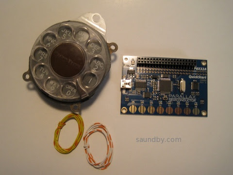
P8X32A Propeller Quickstart Board...Telephone Rotary Dial....Hmmmmmmmm.
Tuesday, July 10, 2012
Gadget Gangster QuickVGA+ for Parallax Propellor

Propeller Quickstart Add-Ons Galore
I mentioned that I picked up a Parallax Propeller Quickstart Board a while ago, and finally got around to playing with it.
Well, I've played with it a lot more now, in part thanks to a cool add-on board from an outfit called Gadget Gangster. I bought a Quickstart VGA+ board from them. It adds a nice VGA port (duh) as well a a PS/2 keyboard port (that's PS/2 as in the old IBM "Personal System/2", not Playstation 2), a stereo audio output, and a Wii Nunchuck port (or the classic controller can go here.) All on one little business card sized board, that fits right on top of the Parallax Quickstart board.
It's a nice combination of features. It's also got places for adding an SD card connector (which I've done), an IR port, and a composite video port.
There's a Pocket Mini Computer project built around this board, that's sort of a C-64 retro-clone kind of system. I look forward to trying that out some time when I get tired of playing with the Wii nunchuck as a raw sensor in software.
One note about that...
The nunchuck software that Gadget Gangster recommended didn't work right out of the box. I've posted na updated version of the nunchuck demo software at the Parallax Propeller Object Exchange, the place where Propeller users post their software for others to modify and use. I modified the demo to use the correct I/O lines for the QuickVGA+ board, and I added a bit of code to make it more clear what's going on with the accelerometers in the nunchuck.
Next, I'll be building up my Gadget Gangster QuickProto board, which came in a bundle deal with a QuickStart board (so, yes, I now have two Quickstart boards. And I ordered one for my daughter, too.
Pennies from Heaven
That's not all the Propellers running around the house, as it happens. While we were at the Parallax Robot Expo, my daughter and I picked up some stuff off the Free table. Among those items were a pair of slightly used Propeller Proto USB boards and one one-off PCB Propeller board that appears to mainly for servos. My daughter has one of the Proto boards and I have the other, as well as the one-off PCB.
I've already added PS/2 mouse and keyboard ports to my Prop Proto board, as well as a composite audio/video adapter. I have plans for this board...
I also found an early rev of the Parallax QuickStart Proto board in my bag of goodies, which I'm planning to use to put a sort of Elf II I/O interface on a Quickstart board. A hex keyboard, a pair of hex displays, some control switches, and hey-ho it's 1977 all over again. :)
Bottom line on the Propeller: It's heaps of fun to play with. Quick and easy. I keep thinking I ought to stop and read the documentation, but it hasn't been necessary, yet.
Monday, June 4, 2012
Parallax Propellor Quickstart Board
When I was at the Parallax Robotics Expo back in April, I picked up a P8X32A Quickstart Board. I've had my eye on the Propeller chip for a long time, I first heard of it before release. But to date, time spent on other things kept me from getting started with it.

The Time Window Opens
Finally, last Friday afternoon, I had a chunk of time open up as a result of being too ill to make a prior commitment. (I can't help but think of how many important things in my life have happened because of time made available through being too sick to do what I was supposed to do, or because I was stranded somewhere without transportation.) The tiny box for the Quickstart board had been living next to one of my computer keyboards for over a month, so I didn't even have to go looking for it. There was a USB cable of the correct type sitting in the drawer next to me. So I started in.
To keep it simple I decided to start out with the Parallax programming environment, Propeller Tool on my Windows 7 machine. I expect to try out Brad's Spin Tool, the other major development tool for Propeller, on my Mac and Linux machines a bit later.
I was pleased to see that it installed everything, the driver for the USB interface chip on the Quickstart board, the IDE, and the serial terminal tool for the Propellor. It says it does that before you download and install, but I was a bit unsure of whether the Terminal program would actually be in there before I actually installed the program.
Once the software was installed, I started it up then plugged in the Quickstart board. I got a ding-dong from Windows telling me it saw the hardware. I was able to find a menu item to report what chip version the software saw, and it saw my chip. I didn't get the message I expected from the documentation at first, a dialog pop-up. That appeared later, the first time I tried to send a program to the board.
About that...
Parallax has a tutorial that runs you through the initial steps of programming the Quickstart board. Aside from the fact that to get to each of the several pages you follow a link from the product page (the pages aren't linked together--that is, when you get to the bottom of one page there's no link to the next one) there's another oversight on these pages as well.
The page gives a short, simple program, describes what it does, then goes on to a slightly more sophisticated program. It tells you about how the editor behaves. But it doesn't tell you how to actually get the code on the chip.
Now, I'm not exactly a first timer here. I looked at the menu and saw "Run" at the top of the screen. But when I chose that I got a list of items, none of which were clearly "compile and run". So I started selecting things at random. I also didn't know whether to expect a simulation environment to start, or how to select between a simulator and the real hardware. I scanned the tutorial web page up to the third program in it, and found no specific instructions.
This is one of those things of which Sherlock Holmes remarked, "the answer is perfectly obvious, once you know it." There is no simulation environment in the free tool, that costs extra (I wish Parallax could follow Atmel's example in providing it with the free tool, the first job I applied an AVR to happened because I was able to use the simulation tool to verify the software timings I needed). And the Run=>Compile Current=>Load EEPROM or Run=>Compile Current=>Load RAM would either have done enough to let me get what I wanted--the sample code running on the target hardware.
But that wasn't clear. I was doing a quick try it and see, so I hadn't spent time with the chip's datasheet yet to learn about how it loads and runs software, what facilities it has for storage, what the implications are of loading EEPROM vs. loading RAM (I didn't even know if they were both program storage, for all I knew one was program storage and the other was for loading an initial state for testing.)
So I was a bit stymied until I just decided to try things at random and see what happened.
At the bottom of the tutorial page is a short table describing the shortcut keys and what they do. Below the actual step-by-step examples that omit instructions for how to compile and run the code. There they describe F10 and F11, for example, and the implications of each choice (RAM or EEPROM).
I managed to get the short initial program (which lights an LED) loaded and running. The LED lit up. There was much rejoicing.
Demo, Demo, Who's Got the Demo?
The next thing I started to wonder about was the demo that showed off the touchpads by lighting up the LEDs when the pads are touched. This hadn't appeared to be pre-loaded like demos often are on other processors. Nor did there appear to be anything obvious among the Propeller code that came with the IDE (another thing I fouond by spelunking, rather than as a result of documentation.) There were no projects with names like "Quickstart Board Demo" or "Touchpad Demo" or whatever. Nearly all the demos appeared to be for hardware I didn't have.
At first I went back to the Quickstart tutorials on the web. I did searches for the demo on the Parallax website and through Google, but the closest I came up with was modified versions of the demo listed in a forum thread. I did find the demo later, but it was only by going back and looking for it time after time that I finally located it today, my fourth day trying, here, on the Parallax Semiconductor Quickstart product page, not on the Propeller downloads page or the Parallax store product page, where there are lots of other downloads but not this one. The location is so subtle, that even after I found it earlier today it just took me five minutes of backtracking to find the right page over again. It's on the linked page, at the end of the list of downloads at the bottom. Direct Link to P8X32A Quickstart LED-Touchpad Demo Software Download
Well, back to last Friday. The demo was interesting to me, but while I was looking for it I came across information about the video capabilities of the Propeller. Frankly, while I'd heard the Propeller did video I just figured it was something along the lines of bit-bashed video like what I've done with several other microcontrollers. I've even generated video from a little Atmel AVR ATTiny12 with nothing more than a software loop and a resistor divider-no fancy shift registers or anything.
Needless to say, it was pretty simple video. No colorburst, no color. But it got some data out of the chip on a two-pin interface nicely (three levels are needed for even black and white video to get the sync signals for timing in addition to the black and white pixel data.)
The Propeller goes way, way beyond this. It's got both NTSC and VGA signal generation hardware on board. And it's not just single bit video, either. It can generate full color at a number of resolutions. This I had to try. But my little Quickstart board doesn't have a video output on it. I looked at the Propeller Demo Board and saw that it had a video interface. It was just a 3-resistor DAC and an RCA jack, so I decided to make one.

At first, the video was pretty wonky. Then I realized I had the resistor that's supposed to go to P13 going to P15. Once I fixed that, it was better, but still not good. The graphics demo ran OK, but one of the text demos wouldn't even sync properly, the other had poor contrast. The thought crossed my mind that either the timing in the Propeller wasn't much better than my old Atari Pong or that the provided 5MHz crystal meant that the timing wasn't right on. But I've learned the hard way, time and time again, to suspect user error first.
I took another look at my too-quick and too-dirty video interface and found that the resistors that were supposed to go between P12 and P13 were swapped. A moment later I had pulled the pins from the plastic IDC header and moved them to the correct positions. This is why doing electronics when you're under the weather is not always a good idea. Fortunately this wasn't a mistake that'd let the smoke out.
Once that was done, the video looked great on all the demos. I then had to make a batter adapter so that I could try it out on the big screen TV in my living room. A quad-AA battery pack came to hand quickly enough, one of the ones with the 9V snap connector on the end. Then I soldered a 9V snap connector pigtail to another IDC header and spliced in an IDC socket pigtail. That way I'd still have a place to put my ground pin from the Q&D video interface without soldering it to the battery connector. As a final refinement, I put a slider switch in line on the positive battery wire to act as a power switch.
Once that and the video adapter were plugged into the Quickstart board, I took it out to the living room and hooked up to a free composite video input. It looked great.
I spent the rest of my time mucking around with the code of the various NTSC video demos. Spin is a really easy language to learn, if you've got any programming experience it'll come easily. It's even simple enough I could easily see teaching it as a first language to new programmers (with a Propellor board on hand, of course, to get the full hardware + software experience!)
Cleaning Up Shop
As mentioned, I have now been playing with my new board for four days. In spite of a couple of minor snags (figuring out what to choose to compile and run my programs, finding the demo for the Quickstart board itself) it's been a very rewarding use of my time. I can see now why people who've been raving about this controller for five or six years are excited about it.
After my first night playing with the board, I learned while reading the Parallax forums that the Propeller could also do RF-modulated video. That's what I spent mid-day Saturday playing with. I put rabbit ears on my big screen (talk about incongruity!) and a pair of jumpers on the RCA jack and managed to receive video from the Propeller from about 25 feet away. What worked even better was an LCD handheld television left over from the analog TV transmission days. I was able to get as far as 10 feet from my back door, a total distance of about 50 feet, and still get good reception. I don't think it's making it as far as the neighbor's house, though (fortunately.)
Yesterday I buckled down to some more structured learning of the Spin language, reading the Propeller Manual and Datasheet, and so on. Today I'm continuing that, working my way through tutorials and such. I also took a look in the goodie bag I filled at the Free tables at the Robotics Expo--there are a couple of Propeller boards in there that I can't wait to find a use for now.
Tweet
The P8X32A Quickstart Board, in the obligatory Altoids tin for scale.
The Time Window Opens
Finally, last Friday afternoon, I had a chunk of time open up as a result of being too ill to make a prior commitment. (I can't help but think of how many important things in my life have happened because of time made available through being too sick to do what I was supposed to do, or because I was stranded somewhere without transportation.) The tiny box for the Quickstart board had been living next to one of my computer keyboards for over a month, so I didn't even have to go looking for it. There was a USB cable of the correct type sitting in the drawer next to me. So I started in.
To keep it simple I decided to start out with the Parallax programming environment, Propeller Tool on my Windows 7 machine. I expect to try out Brad's Spin Tool, the other major development tool for Propeller, on my Mac and Linux machines a bit later.
I was pleased to see that it installed everything, the driver for the USB interface chip on the Quickstart board, the IDE, and the serial terminal tool for the Propellor. It says it does that before you download and install, but I was a bit unsure of whether the Terminal program would actually be in there before I actually installed the program.
Once the software was installed, I started it up then plugged in the Quickstart board. I got a ding-dong from Windows telling me it saw the hardware. I was able to find a menu item to report what chip version the software saw, and it saw my chip. I didn't get the message I expected from the documentation at first, a dialog pop-up. That appeared later, the first time I tried to send a program to the board.
About that...
Parallax has a tutorial that runs you through the initial steps of programming the Quickstart board. Aside from the fact that to get to each of the several pages you follow a link from the product page (the pages aren't linked together--that is, when you get to the bottom of one page there's no link to the next one) there's another oversight on these pages as well.
The page gives a short, simple program, describes what it does, then goes on to a slightly more sophisticated program. It tells you about how the editor behaves. But it doesn't tell you how to actually get the code on the chip.
Now, I'm not exactly a first timer here. I looked at the menu and saw "Run" at the top of the screen. But when I chose that I got a list of items, none of which were clearly "compile and run". So I started selecting things at random. I also didn't know whether to expect a simulation environment to start, or how to select between a simulator and the real hardware. I scanned the tutorial web page up to the third program in it, and found no specific instructions.
This is one of those things of which Sherlock Holmes remarked, "the answer is perfectly obvious, once you know it." There is no simulation environment in the free tool, that costs extra (I wish Parallax could follow Atmel's example in providing it with the free tool, the first job I applied an AVR to happened because I was able to use the simulation tool to verify the software timings I needed). And the Run=>Compile Current=>Load EEPROM or Run=>Compile Current=>Load RAM would either have done enough to let me get what I wanted--the sample code running on the target hardware.
But that wasn't clear. I was doing a quick try it and see, so I hadn't spent time with the chip's datasheet yet to learn about how it loads and runs software, what facilities it has for storage, what the implications are of loading EEPROM vs. loading RAM (I didn't even know if they were both program storage, for all I knew one was program storage and the other was for loading an initial state for testing.)
So I was a bit stymied until I just decided to try things at random and see what happened.
At the bottom of the tutorial page is a short table describing the shortcut keys and what they do. Below the actual step-by-step examples that omit instructions for how to compile and run the code. There they describe F10 and F11, for example, and the implications of each choice (RAM or EEPROM).
I managed to get the short initial program (which lights an LED) loaded and running. The LED lit up. There was much rejoicing.
Demo, Demo, Who's Got the Demo?
The next thing I started to wonder about was the demo that showed off the touchpads by lighting up the LEDs when the pads are touched. This hadn't appeared to be pre-loaded like demos often are on other processors. Nor did there appear to be anything obvious among the Propeller code that came with the IDE (another thing I fouond by spelunking, rather than as a result of documentation.) There were no projects with names like "Quickstart Board Demo" or "Touchpad Demo" or whatever. Nearly all the demos appeared to be for hardware I didn't have.
At first I went back to the Quickstart tutorials on the web. I did searches for the demo on the Parallax website and through Google, but the closest I came up with was modified versions of the demo listed in a forum thread. I did find the demo later, but it was only by going back and looking for it time after time that I finally located it today, my fourth day trying, here, on the Parallax Semiconductor Quickstart product page, not on the Propeller downloads page or the Parallax store product page, where there are lots of other downloads but not this one. The location is so subtle, that even after I found it earlier today it just took me five minutes of backtracking to find the right page over again. It's on the linked page, at the end of the list of downloads at the bottom. Direct Link to P8X32A Quickstart LED-Touchpad Demo Software Download
Well, back to last Friday. The demo was interesting to me, but while I was looking for it I came across information about the video capabilities of the Propeller. Frankly, while I'd heard the Propeller did video I just figured it was something along the lines of bit-bashed video like what I've done with several other microcontrollers. I've even generated video from a little Atmel AVR ATTiny12 with nothing more than a software loop and a resistor divider-no fancy shift registers or anything.
Needless to say, it was pretty simple video. No colorburst, no color. But it got some data out of the chip on a two-pin interface nicely (three levels are needed for even black and white video to get the sync signals for timing in addition to the black and white pixel data.)
The Propeller goes way, way beyond this. It's got both NTSC and VGA signal generation hardware on board. And it's not just single bit video, either. It can generate full color at a number of resolutions. This I had to try. But my little Quickstart board doesn't have a video output on it. I looked at the Propeller Demo Board and saw that it had a video interface. It was just a 3-resistor DAC and an RCA jack, so I decided to make one.
It doesn't get much quicker and dirtier. It took longer to pull the parts than to assemble.
At first, the video was pretty wonky. Then I realized I had the resistor that's supposed to go to P13 going to P15. Once I fixed that, it was better, but still not good. The graphics demo ran OK, but one of the text demos wouldn't even sync properly, the other had poor contrast. The thought crossed my mind that either the timing in the Propeller wasn't much better than my old Atari Pong or that the provided 5MHz crystal meant that the timing wasn't right on. But I've learned the hard way, time and time again, to suspect user error first.
I took another look at my too-quick and too-dirty video interface and found that the resistors that were supposed to go between P12 and P13 were swapped. A moment later I had pulled the pins from the plastic IDC header and moved them to the correct positions. This is why doing electronics when you're under the weather is not always a good idea. Fortunately this wasn't a mistake that'd let the smoke out.
Once that was done, the video looked great on all the demos. I then had to make a batter adapter so that I could try it out on the big screen TV in my living room. A quad-AA battery pack came to hand quickly enough, one of the ones with the 9V snap connector on the end. Then I soldered a 9V snap connector pigtail to another IDC header and spliced in an IDC socket pigtail. That way I'd still have a place to put my ground pin from the Q&D video interface without soldering it to the battery connector. As a final refinement, I put a slider switch in line on the positive battery wire to act as a power switch.
Once that and the video adapter were plugged into the Quickstart board, I took it out to the living room and hooked up to a free composite video input. It looked great.
I spent the rest of my time mucking around with the code of the various NTSC video demos. Spin is a really easy language to learn, if you've got any programming experience it'll come easily. It's even simple enough I could easily see teaching it as a first language to new programmers (with a Propellor board on hand, of course, to get the full hardware + software experience!)
Cleaning Up Shop
As mentioned, I have now been playing with my new board for four days. In spite of a couple of minor snags (figuring out what to choose to compile and run my programs, finding the demo for the Quickstart board itself) it's been a very rewarding use of my time. I can see now why people who've been raving about this controller for five or six years are excited about it.
After my first night playing with the board, I learned while reading the Parallax forums that the Propeller could also do RF-modulated video. That's what I spent mid-day Saturday playing with. I put rabbit ears on my big screen (talk about incongruity!) and a pair of jumpers on the RCA jack and managed to receive video from the Propeller from about 25 feet away. What worked even better was an LCD handheld television left over from the analog TV transmission days. I was able to get as far as 10 feet from my back door, a total distance of about 50 feet, and still get good reception. I don't think it's making it as far as the neighbor's house, though (fortunately.)
Yesterday I buckled down to some more structured learning of the Spin language, reading the Propeller Manual and Datasheet, and so on. Today I'm continuing that, working my way through tutorials and such. I also took a look in the goodie bag I filled at the Free tables at the Robotics Expo--there are a couple of Propeller boards in there that I can't wait to find a use for now.
Subscribe to:
Posts (Atom)


 Webomator.com: Backward into the