Showing posts with label design. Show all posts

Thursday, May 29, 2014

ZBrush Export to Unity 3D, Mesh + UV

ZBrush is a great tool in many ways. But there are other ways in which it is infuriating. It is mysterious about what it is doing in many cases, and the documentation on these mysteries is usually nothing more than a longer version of the text on the buttons and menus.

UV maps are one of the places where the data is slim, and the documentation tells you nothing about what's going on with the choices you make. It's like that Sherlock Holmes quote about it making perfect sense once you already know the answer.

On top of that, there's a lot of FUD about transferring data from ZBrush to Unity. Certainly there are other programs for which Unity makes the process more or less seamless, but ZBrush is perfectly capable of providing all the same data to Unity. It's just a matter of knowing the correct process. Which is difficult with ZBrush if you're just trying it on your own, because there are so many settings for which ZBrush doesn't show you directly the effects of your choices. You have to keep going back and forth between ZBrush and Unity--does this work? Does that work? What about that? On and on. And at each stage you're guessing, because you can't look at what comes through in Unity and say, "Oh, I see the problem. I need to just do -that-!" It's just a mishmash of unmatched data.

Well, I spent two solid days experimenting. Trying out different things, getting something to work, making sure I can do it twice in a row and have it work both times. Researching on the internet to see if someone else had a better way, and so on. You don't need to hear the whole litany--getting it done was my job, now here's the results for you to take advantage of so that you can get on with your project.

I'm using Unity 4.3.4f1 and ZBrush 4R6 for this. I'm covering just exporting the object mesh and its UV texture here. A normal map works similar to the UV texture--the key point being that it has to be vertically flipped to align with the mesh in Unity. If you're interested in another post that covers normal maps specifically, email me or leave a comment and I'll do it.

You've Got an Object in ZBrush

So your object is sculpted and polypainted in ZBrush, now you want to drop it into Unity.

First, you've got to convert the polypainting into a separate image file that will wrap around your object's mesh in Unity. This is called a UV texture. What makes things confusing is that it's often called a UV Map in casual usage, but a UV map is actually something else. The UV Map is the relationship between pixels on a UV Texture and points on the mesh. In ZBrush these are separate and distinct items. In many other programs, the UV Map and UV Texture are conflated to simplify things. Which makes it seem like ZBrush has an extra step when creating UV Textures for Unity and other 3D software.

Before beginning, save your project and your tool(s) in ZBrush. There will be opportunities for things to get messed up or confused.

Create the UV Map


0: Open up UV Master in the ZPlugin menu.

This is where we'll create the UV Map, the Texture itself comes later.

1: Click Work on Clone

This takes care of a bunch of stuff to prepare for making the UV without disturbing your original object. I've screwed up several meshes trying to go without it. My advice is to just use it, it makes things easier.

2: Turn on Symmetry if your object is symmetrical.
Symmetry will try to make a symmetrical UV map, which results in a symmetrical UV texture that's easier to edit by hand. If your object is just sort of symmetrical, you might give it a try, too.

3: Click the big Unwrap button.
This will unwrap the current tool. My advice is to work one tool at a time, and to reduce the number of tools to the minimum necessary before getting to this point to reduce the repetition of exporting meshes and maps.

4: Click Flatten to have a look at the shape of your UV map.
You will see a wireframe of the UV map, this is the form into which your object's polypainting will be projected to make a UV texture. If you're expecting to do any hand editing of the texture's details, make sure that the forms are not too distorted and that seams are not crossing critical areas of the mesh, like across the face of a character. If they are, you can use Control Painting to get a better mesh.

I'm not going to cover that in detail, there are good videos on this at Pixologic and on YouTube, but the short form is:

  • Click Unflatten to get the controls back.
  • Click Enable Control Painting
  • Click Protect, then draw red on the parts of your mesh where you absolutely don't want a seam in the UV map (like the face of a character.)
  • Click Attract, then draw in blue the areas that you'd like the seam to be (like the back of a character's head, or under their chin.)
  • Click Unwrap again and check the results using Flatten.

5: Click Unflatten to get your controls back.

6: Click Copy UVs to put your UVs from the Clone on the Clipboard.


You've now created a UV map, which you need to apply to your original object to guide the creation of a UV texture from its polypainting.


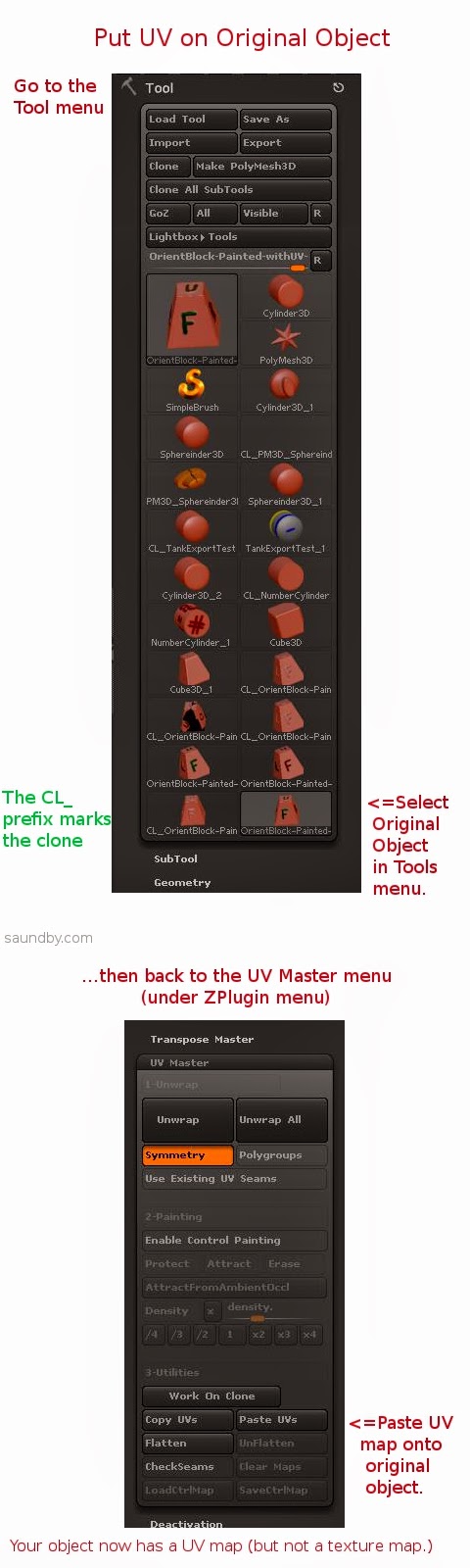
7: Select your original object from the Tool menu.
This will bring it back into the Document view and make it the active object. If something's wrong, or you can't find it, reload it using Load Tool (because you saved it before starting like I advised, right?)

8: Click Paste UVs in the UV Master menu.
This puts the UV from the Clone that's on the Clipboard on your object. It's now ready to have its texture map made from the polypaint on it.

9: Save your tool. Give it a distinctive name, like MyTool-withUVs.ztl.

10: Take a deep breath. The rest is pretty easy.


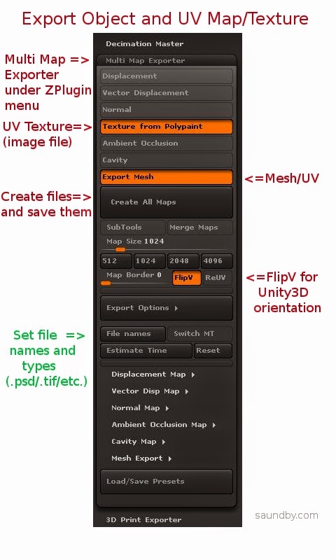
11: Open Multi Map Exporter under the ZPlugin menu.

12: Choose the things you want to export. Mesh and Texture from Polypaint for this example.

13: Choose FlipV to orient maps correctly for Unity.

If you want to have your map files in a specific format, select it in the Export Options and file names sections.

14: Click Create All Maps to create the UV texture and to save the mesh as an .OBJ file. This is one of the most poorly worded bits of button text in ZBrush. Even just "Save" would have made more sense. Oh, well, if we start talking about what's screwy with ZBrush's UI, we'll never finish.

15: Import assets into Unity (Assets=>Import New Asset...).


Gotchas

OK, that's the process. Having it all written out in detail makes it look worse than it really is, it actually happens very quickly once you know it. It's those first few passes that are a problem.

One of the things that really slowed me down in ZBrush is the fact that ZBrush doesn't tell you anything inside ZBrush about what the orientation of the UV map is relative to the base orientation of the mesh. If you open the Tools=>UV Map menu and start clicking the buttons like FlipV, FlipH, Cycle UV, Switch U<>V, it's easy to get lost really quickly as to which transformations you've applied. And there's no simple way to set it back to its base orientation.

Finally, what I ended up doing was creating the UV texture, while applying no transformations at all, then I opened it in GIMP & performed all the tranformations there, saving a clearly marked file for each. Then I pulled the mesh into Unity as well as all the versions of the map. I just drug maps onto the mesh object in Unity until I got the right one (FlipV.)

Colors from ZBrush

To make sure, I saved the map from ZBrush again with FlipV on, and it worked. But then I noticed something. The colors were off on part of the map in Unity. It looked OK in ZBrush and GIMP, but for some reason the color encoding came across wrong in Unity.

Left, Texture map in .psd straight from ZBrush. Right, texture map opened in GIMP and re-saved.

The quick fix was to load the map in GIMP then re-save. It may also be possible to use other file types, like .tif, and have the colors work out perfectly from ZBrush.

The Effects of UV Orientation
The map on the left was saved with FlipV on, the one on the right was saved without. If you get an object looking like the one on the right, check your UV map's orientation, or flip it vertically in an image editor (flip, don't just rotate 180.)

Mesh Orientation

The mesh orientation will get rotated front-for-back when going from ZBrush to Unity, too. It's just a 180 degree rotation, so it's not difficult to fix, just turn it around. If it's facing the camera in ZBrush, it'll be facing away when it comes into Unity.


The object on the left has been rotated to bring the 'F' side (Front) to face the camera, as it was saved in ZBrush, the one on the right is how it came into Unity.

Torn Edges on UVs

You'll notice in that picture of the back of the block above that there's some ragged stuff showing at the edges of the UV map. At first I blamed bringing the map through GIMP, but it does that straight from ZBrush, too. Fortunately the fix for that is simple, too.

For this simple texture, I just did a flood-fill of the black areas of the UV map with the background color (white). With a more complex texture, I would have used smudge or something like to bleed out the edges of the map a few extra pixels.

Map on the left has been cleaned up, UV on the right is as original, with visible seams.

Here are the maps used in the above image:


The original UV texture map from ZBrush.

The UV texture map with the black areas flood-filled with the foreground color of the object.

That's a Wrap

I hope that helps. If you feel I've been unclear anywhere here, or missed something important, please leave a comment or drop me an email message. If I've been helpful, let me know that, too!

Good luck with your ZBrush and Unity endeavors!

Monday, January 6, 2014

Parallel Processes on the XMOS StartKIT

XMOS StartKIT board and its shipping box.

XMOS sent me a free StartKIT development board just in time for Christmas. Now that the festivities are over, I've had a chance to get started with it. It's a bit frustrating because XMOS's documentation has the necessary information scattered rather broadly, and documents that you'd expect to contain certain pieces of information do not.* It's all there, just poorly organized & often hidden in long documents where you wouldn't expect it.

That said, the hardware is exciting in its potential. Once I got through the basic tutorial stuff I went to write a simple multiprocessing program--handing over the blinking of two LEDs on the board to two independent processes.

Here again I ran into documentation deficiencies. XMOS presents code examples in their docs as snippets, not full programs. This leads to misunderstandings due to lack of context. I was able to get a program going, on the third attempt. The first syntax I tried created two dependent processes. The second's syntax was not accepted even though it was copied from a sample snippet--it had a variable that needed to be declared, but I didn't know what type to declare it as, and the declarations are left out of the snippets. The third try worked, but only after enough time spent reading and time spent doing some fortunate guesswork to have gotten a lot further with another, better documented hardware platform.

Lighting a Candle While Cursing the Darkness

I still think this is the right platform for the initial ideas I had for it, though. So as I press on, step by step, in implementing those ideas, I'm going to document what I learn & hope to save others time and trouble. I've made a couple of resolutions about the code, similar to those on the code for my Begin with Java blog:

1. All examples will be presented as complete, compilable programs.

2. All examples will use multiprocessing syntax and structure.

Look for this code to appear on my website, saundby.com soon.

Until then:

Don't follow the example syntax XMOS uses of writing your code inside main(). All main() should contain is channel declarations and par{} blocks. Put all your code into functions to be called inside par{} blocks.

The code for the dual process LED blinker:

/*
 * LED Tests.xc
 *
 *  Created on: Jan 5, 2014
 *      Author: saundby
 */
#include <xs1.h>

out port    p1              =   XS1_PORT_1A;    //PORT 1A for D1 LED
out port    p2              =   XS1_PORT_1D;    //PORT 1D for D2 LED

void led1(){
    while(1){ //run forever
        p1 <: 1; // LED D1 On
        delay_milliseconds(200);
        p1 <: 0; // LED D1 Off
        delay_milliseconds(200);
    }
}

void led2(){
    while(1){ // run forever
        p2 <: 0; // LED D2 Off
        delay_milliseconds(50);
        p2 <: 1; // LED D2 On
        delay_milliseconds(350);
    }
}

int main(void) {
    // Note: put the 'forever' loop in each of the 
    // individual tasks, not out here.
   par{
       led1();
       led2();
   }
   return 0;
}

* It took me forever to find the electrical characteristics of the I/Os in the data sheets, but they are there. There just isn't a data sheet for the specific IC used in the StartKIT, which is a unique item not for sale separately. Personally, I consider it a major oversight to not either provide a data sheet for this specific IC or to include that information in the Hardware Manual for the StartKIT. Based on the scuttlebutt in the forums, I'm using the datasheet for the XS1-A8A-64-FB96 (PDF) as the closest analogue.

Tuesday, November 26, 2013

Why Electronics Took Over the World


How did we end up in a world where computers are everywhere?

Originally, we had vacuum tubes as electronic components. Each of these has to be hand-made. When you consider that even the most basic computer, about the power of a programmable calculator, requires about 4000 electronic switches in it (including some basic control, memory, and interface circuits), you can see that needing 4000 hand made parts is going to get expensive. And that's before you wire them together into a working computer. It's like having to hire a team of scribes every time you want to get a new book.

Each of those tubes is like a decorated capital drawn by a scribe.

Transistors were a big step forward. Transistors aren't made one at a time by hand. Packaging them involved some hand work back when they were new, but the guts of them were produced en masse. Making transistors was like printing a sheet covered in letter "B" so that you could cut them up to have a letter B to stick wherever you need one. Similarly, transistors are made in a large group, which is then cut up into individual transistors then packaged for use.

So why not print the equivalent of a small piece of often-used text, rather than cutting it up into individual letters? This is the basis of the integrated circuit. It was another step forward in reducing the cost of electronics manufacturing. The first circuits were like having commonly used words, in complexity. Over time, technology advanced to allow more and more sophisticated circuits.


Eventually the circuits got more and more complex, and more useful. Building a computer got to be about as complex as creating a book on a typewriter. That means it took patience, and skill, and it was still expensive, but not nearly as expensive as hiring a team of scribes.

Each integrated circuit has from a few to as many as a few hundred transistors on it at this point. Building a basic computer circuit could be accomplished with a couple of hundred ICs.

The next step was a big one. Integrating the entire guts of a computer onto a single die, then printing them not one at a time, but by the tens then the hundreds at a time.

In the mid 1970s enough transistors were printed together, in the right circuits, to make a basic computer. When added to some memory (which was another technology that had recently benefited from the improvements in integrated circuits), a few ICs for control and for interfacing to the outside world, a complete computer could be built out of a handful of integrated circuits. Like my MAG-85 computer project, which uses about 10 ICs to build a basic 70's style computer.

But that wasn't enough. It was enough for calculators and very simple computers that require someone with a high level of skills to get the most out of them. If we'd stopped there, only very technical or very driven people would have computers. We had to increase their complexity to make them more capable, and easier to use.

Since then, we've improved our "printing processes" to allow us to produce integrated circuits that contain not just a few thousand "switches", but billions. Your computer, cell phone, or tablet contains the equivalent of billions of vacuum tubes. And yet, those billions of sub-microscopic electronic switches all together require less electrical power to operate than one single vacuum tube. They also generate less heat.

If we put the entire world population to work building electron tubes as fast as they can, we couldn't produce enough tubes to reproduce the computing power of a single cell phone in a year. In part because we couldn't build tubes that can switch as quickly as the transistors in a cell phone.
the guts of a simple vacuum tube
Imagine building a few billion of these, by hand. Image courtesy RJB1.
But the computer in the heart of that cell phone is one chip that was printed alongside hundreds of others just like it in a mass production process that's very similar to printing. Many of today's computer chips literally cost less to make than a printed magazine or book. Far less, usually.

This triumph of manufacturing, reducing electronics to a simple, inexpensive, high volume printing process, is why we have computers everywhere from our cell phones to our irons and dishwashers. They're cheaper to build than the parts they replace.

Have a look at a current computer chip sometime. Inside it are several billion man-made structures. You could look at them with a microscope if the top were removed, but you would only see patterns, not individual elements. The individual elements are too small to see in visible light now.
There are several billion man-made things in this image.

Tuesday, November 19, 2013

ZBrush for CNC Got Better

Yesterday, I learned that ZBrush (my 3D design program) now has an extension that lets it directly export files I can use with my Computer Aided Manufacturing (CAM) programs. I spent most of my work time today testing the output of various designs to see how they looked.

ZBrush has this 'built-in' since version 4R6 came out, it was available as a plug-in before, but since it calls itself a 3D printing plug-in, I ignored it, assuming it was software to sent object data to one or more of the commercial 3D printing services, like Shapeways. Turns out it's an exporter for standard 3D object file formats like .stl.

This is a huge improvement for my workflow of going from design to a finished part prototype in the real world. Before I had to use a very complex conversion program. Its control panel makes the flight deck of a 747 look simple. And if I didn't get the settings just right, I could get some really nasty effects in the final machining. Using the same settlings over again doesn't work, I had to adjust things based on the size of the object, the scale of features on it, the size of the material it would be cut out of, the relative size of the tool, etc., etc.

Now that difficult & frightening step is gone. I do a couple of passes to simplify the 3D object design as much as possible without losing detail (which I was doing anyway, it speeds up everything later), set a couple of simple settings in the exporter, like the real-world size the final object will be, then export.

The resulting files load just fine into the two different programs I use that create the list of instructions for my CNC machine to cut the 3D object out of a solid block of some material (usually a polyurethane plastic). I did a dry run to set up two test files tonight--doing everything short of actually making the parts. Tomorrow I plan to make an actual part from a new file as a final test. Probably something fun.

For those interested in trying this at home, I use both MeshCAM and Vectric's Cut3D for CAM. Cut3D is my usual preference, though I'm using an older version of MeshCAM (4). I prefer Cut3D's interface for setting tabs, and its included machining preview.

Both produce excellent GCode for my CNC (a MicroCarve A4 driven by EMC2 and a Gecko G540 controller.)

For doing image depth maps, I use EMC2's built in facility, though if you want to bypass the copious experimentation & two pages of notes I use to get it looking good, you might want to look into one of the dedicated commercial programs for this.

Thursday, November 14, 2013

Ted Nelson's Computer Lib 40th Anniversary to be Honored at Chapman University

I forgot to mention an additional item in my post on meeting Ted Nelson. Chapman University will be honoring the 40th anniversary of the publication of Computer Lib on April 24th-26th, 2014, presumably at Chapman's campus in Orange, California.

Here are images of the flyer (once again, apologies for the fold. I put it in my hip pocket since I wasn't toting anything else to carry things at the time.)


Wednesday, November 13, 2013

Lee Felsenstein at Homebrew Computer Club Reunion

Lee was the MC at the main part of the club meetings back in the day, and he reprised that role on the night of the HCC reunion. He was also the designer of the computer in that day that I most desired, the Sol 20 Computer. I loved that system--the look, the keyboard, its operation.

Image by cellanr
There were just two things you wanted to know about the Sol to make life happier: Build the fully expanded system right at the outset. Opening up the heart of the system to expand it later was a major PITA. The other? Use someone else's disk subsystem. Though with the information available today a Helios disk subsystem could probably be made to work.

I still have the sales brochures for the Sol 20. I pull them out every now and then to drool over them again. Part of it is nostalgia, but part of it is the great design itself. Actual Sol 20s sell for more than I can afford, but perhaps I'll build myself a look-alike system from sheet metal and walnut wood sometime, anyway, and print up a nice black name badge.

I still have an Osborne 1 computer. This one is one I got only relatively recently. It is pretty well maxed out on upgrades (disk upgrades, video upgrades, etc.) and is a pleasure to use. It's not as pretty as a Sol, but I enjoy showing it off in current day computer classes. The kids love it--especially the floppy disk drives and the tiny screen. But...they get hooked on Zork.

Lee Felsenstein Today

In our conversation last Monday, Lee showed me a project he's working on today as an educational tool. It's a programmable logic simulator, targeted at middle school students. What Lee showed me was a pair of printed circuit boards that have captive fasteners to clamp them together around a plastic matrix. The matrix holds surface mount diodes, which the students can place into the matrix to program it. In essence, it's a 16 by 8 programmable logic array that is programmed through physically locating the diodes.

OK, I know that sounds totally abstruse to many of you, so let me tell you what makes this a great idea, and why your middle schooler ought to know about this stuff even if you've gotten through life without having to so far (assuming you don't know already).

The core of computers are built out of logic circuits. The memories feed the logic circuits with data (in current designs--it doesn't have to be that way though it's presently the assumption), in essence, the programmable logic is the complement to the memory. This analogy of the logic and memories being complementary components of a computer holds on many levels. It's possible to build logic out of memories--I've done it--but it's not efficient.

Initial education in logic circuits can be accomplished with a simple breadboard and some logic chips. A few AND chips, OR chips, NAND chips, inverters, and so on. Add some resistors and LEDs and the kids are off and running. For a little while. Once they master this, and understand what's going on, they immediately start expanding their ideas.

Then a problem hits. More chips and more wiring between them mean more complexity, and more difficulty in realizing their ideas.

At this point, it's possible to introduce them to programmable logic devices. Teach them that the logic functions they had in the ICs live inside the PLDs, and that they can program the devices rather than run wires. The problem is that this is a big, big jump up in abstraction level, especially for a kid in the middle school age bracket (which is the perfect age to introduce this stuff, which I'll go into later.)

Whereas Lee's invention maintains a physical element. The programming is accomplished by manually placing diodes into a matrix, rather than typing characters on a screen then punching the 'program' button to dump it to a Flash PLD. This keeps it from getting too abstract, encourages experimentation, and maintains the hand-on element that's necessary for students in the 9-13 years age range.

Building Blocks of Electronics

Electronic logic is building blocks. Your kids play with building blocks, right? They start with simple structures to learn how to build more complex structures. Before long, they can use every single piece they've got building large, complex structures. Once the individual blocks and a few simple ways of interconnecting them are understood, they can take off and make great big projects that reach to the ceiling.

It's the same with electronic logic. It's a collection of simple building blocks. The problem is, the complexity of assembly is a little greater. Enough that once you get past a certain level (I'd say 20-30 ICs), it gets progressively more difficult to implement your ideas. The ideas out-race the ability to construct.

This shouldn't be an obstacle. The ideas should be allowed to continue to grow, without removing the physical aspects that make the activity interesting.

The Lee Felsenstein Magic

Lee has hit a sweet spot here. With all the excitement about the Raspberry Pi (which I will save my criticisms of as an educational tool for a future article), Lee's project should have that sort of excitement going for it. This is about students building their own processor. This knowledge is important. This is what the people who caused the microprocessor revolution used to cause the revolution in our lives. This is the knowledge that put a CPU in your telephone, your oven, and your iron. This is what tunes your radio.

Assembling a processor from random logic is a huge project. Yes, people still do that (I've even build a very, very simple one from racks of relays, myself, under cover of testing those relay racks and their support wiring after installation.) Building your own processor with a PLD is a lot easier, once you understand the building blocks.

Lee explains himself well on his project page. Have a look. I will be following the progress of the project.

And I'm really glad I got a chance to meet up with Lee again after all these years. He was one of my mentors and inspirations in my youth, just as he describes those who mentored him. It seems to be a common thread that those of us getting older want to assist the younger generation just as we were assisted when getting started in technical pursuits (as hobbies--the jobs came later.)

And if you're raising a kid--don't just foist off software on them as something to play and "learn" with. Software isn't reality. I've designed any number of computers on paper and in software, and then go on to build far fewer of them. Because software and paper aren't the real thing. The real thing has all sorts of little niggles and oddities that you'll never learn about in any way other than doing the real thing. Teach your kids to solder, use solderless breadboards, and use real components at all levels of complexity. Don't try to do too much at once, start with kits then move your way toward recreating circuits on breadboards then to soldering them on prototyping boards.

But do the real thing. Right alongside your other crafts projects. Because electronics is just as much a craft with some useful products as is crochet or embroidery (both of which I do) or quilt-making or sewing (which some of those close to me do). And most of all, have fun!

Tuesday, November 12, 2013

Ted Nelson & Computer Lib at Homebrew Computer Club Reunion

I had a great time at the Homebrew Computer Club Reunion last night, which, I learned, was made possible by a Kickstarter (thank you, KS backers!)

One of the great conversations I had there was with Ted Nelson, author of Computer Lib/Dream Machines and his wife, Marlene Mellicoat. My wife and I had a wonderful time speaking with them. Ted has published a new edition of Computer Lib. It's not a reprint from scans of the original, but a new printing from the original negatives. It's as clear and sharp as the original was back when, possibly even better. It's in the same large format, as well, not scaled down for the size of paper that happens to be cheap and convenient for most books.

Sorry about the fold, I only had my hip pocket as a place to put his flier last night.
I was working so hard at being social last night it didn't even occur to me that I could probably have purchased a copy directly from him right then. I saw that he had a number of copies in his bag, too. It's little things like this that I always think of when people tell me how smart I am. Yeah, about some things, maybe, but about other things I'm not so much.

Nevertheless, I'm going to purchase it now, after the event. I read someone else's copy back when, having noticed it as a pillar on a bricks and boards bookshelf among a number of copies of The Fabulous Furry Freak Brothers (Fat Freddy's Cat was my favorite of the crew.) Now I'm looking forward to having a Computer Lib/Dream Machines book of my own.

If you're not familiar with Ted's work, I strongly recommend correcting that. The web could be so much more than it is, and require far less human "curation" than it does, if it hadn't turned into the mishmash mess of information without proper structure that it has become. I'd say more, but rather than reading my take on what he thinks, go to the source:


Hopefully I'll have a chance to post more about last night's event in future articles. There was so much packed into so little time that my head is still spinning from it. (They managed to recreate the atmosphere of the original meetings perfectly in that regard.)

It was great that my wife got to hear Ted speak during the formal presentation portion of the evening, too. I got to hear him speak a few times back when, he's a dynamic and engaging speaker. He makes you think about how things could be, possibilities that are better than reality. Now we have hearing Ted speak as a shared experience.

Thursday, July 19, 2012

8085 Monitor Code and Other Distractions

I've been working on an 8085 microprocessor project for about 3 years now. It started with a simple circuit on a breadboard, moved to my HP Logic Lab, where it became a real computer, then got built into a permanent version on a prototyping PC board.

I've been documenting the thing since it moved to the Logic Lab on my web site, posting how-to articles on building both versions (the hardware is identical, only the construction method is different), as well as software to control the hardware.

Where I've come up short is putting together a sort of unified OS for the system online that allows software to be developed right on the system itself, as well as any high level languages. I've been writing lots of software for my own use with the system, mostly hand-coded using my assembly coding forms and my 8085 Pocket Reference Card. But I keep either getting distracted from or otherwise dodging the job of integrating all the software bits I've already got into a simple "monitor" program (sort of a mini-OS for machine language) for the system.

Part of it is the usual life distractions. I've been sitting next to a wild fire this past week, for example. And then I've got lots of other electronic toys I like to spend some time with. Each one has its own appeal.

Before the fire, and a bit during (when I was taking a break from cutting ever more brush around my property) I've gotten back to work on putting it together. The biggest part is the part that reads the keyboard, determines the current system state, and dispatches keystrokes and execution to the right place. All the hardware interfaces are already in place, most of the basic system routines are in place (timing/delays/string handling), etc. So the "glue" is pretty much all that's needed. And I got it about halfway done before the fire started, I'm writing the code that actually takes actions for each mode, or simply hands over the necessary info to user apps running on the system.

So, if I can get time away from deck repairs on my house this weekend (now that it looks like it's unlikely to burn down or that I get evacuated), I'll be trying to wrap up and test that code.

Small Thing, Big Obstacle

The other thing I'm looking forward to is replacing some of the switches I put on the MAG-85. I put in switches for various interrupts about two years ago, and the switches themselves turned out to bounce and make so much noise that I've given up on them. No amount of debouncing, hardware or software, within reason has made them reliable. I'd hate to have someone else construct a MAG-85 and have to deal with this. It's been a thorn in my side ever since I added them, and took a lot of the fun out of the permanent hardware project for me (on the breadboard version, I used some old keyswitches out of a knackered Mac Plus keyboard, they worked great with only the most minimal hardware debounce. But I figured I could hardly specify 25 year old keyswitches in a project that others might want to build.

I'm expecting a shipment of a bunch of different switches tomorrow that I can test and select from to replace the awful switches I have now. So I can put that behind me (and probably re-simplify the circuit to take out a bunch of the extra parts I put in to try to deal with the noise on these switches.)

Frankly, the old switches are something I'd about hesitate to use in a doorbell circuit, never mind real electronics.

Monday, May 7, 2012

ZBrush: Finding the Hidden Spotlight

As I've commented recently, I'm working on learning ZBrush and running into landmines and frustrations regularly. The program is incredibly powerful, so I'm hoping all the time and frustration will be worth it in the end. Though I'm less than convinced it'll be so at this point. Presently I'm a bit over two weeks in, with about 60-70 hours using it and a lot of additional time reading docs and watching training videos.

Spotlight

Among the tools I set for myself to try out today is Spotlight, a very powerful-looking tool featured in this impressive video. After getting the "sizzle" on Spotlight from that and some other videos, I tracked down some more pedestrian stuff that I hoped would let me see how to actually do a little of that.

For example, this great video, which takes things step by step and at a pace where you can actually see what is being done. Unfortunately, when I tried to follow along on my own, there was a missing step.

Getting the texture into Spotlight.

Which opened another can of worms...

Where is the Spotlight?

I opened my Lightbox, selected my texture, and Spotlight was nowhere to be seen. So I took a look at the Pixologic site to find some written documentation. I found what seemed to be just the thing. I read carefully through the instructions, particularly noting:

You first need to load your textures using the Texture palette or Light Box.

then, later the detailed instructions:

3. In the Texture palette, load or import a source texture with which you will paint on the model.
4. Also in the Texture palette, click on the Add to SpotLight button. Your texture will be displayed as an overlay on the document and the SpotLight widget will appear. An alternative is to double click on a texture of your choice in Light Box.
Um, no.

First, double-clicking on the texture in Lightbox did not bring up the Spotlight widget. Then, looking in the Texture Palette, and in the Texture tool on the side of the screen--in case I misunderstood--revealed no "Add to Spotlight" button.


The Hidden Spotlight Button

Well, I spent a fair bit of time reading FAQs and other information trying to find out why there were no visible parts of Spotlight in my ZBrush. Finally, I found an answer well down in this thread. The "Add to Spotlight" button is there, it's just not labelled, looks like it is inactive, and the icon makes no sense:

The icon for


To be fair, it does say "Add to Spotlight" off to the side if you hover over it. But then, what's to induce me to hover over everything in the 90 square hectares of ZBrush's menus just to see if I can find a button by spelunking? Especially when it's greyed out so as to look dead, inactive, unavailable, and, in subtle grey-on-grey, almost invisible?

Clicking on this added the texture to Spotlight, brought up the Spotlight wheel, and let me get on with walking into a new set of frustrations. But it was progress.


Endemic Problems

This relates to several of the endemic problems with ZBrush, particularly its user interface. There's a mix of text and image icons. The image icons are seldom intuitive. The color scheme makes icons look inactive when they're not.

At a larger level ZBrush has the problem of being a huge tool box with no organization to it. There are multiple ways of doing things, with no clear way of choosing which will get the desired results, or do so in the most time-effective fashion. Likewise, the only way to determine what something will do is to experiment, experiment, experiment. And with the number of options and settings (spread through several different "palettes" or menus) there's no guarantee that you can recreate something you've seen someone else do, or even recreate your own work later if you happen to have changed a setting three menu levels down earlier then forgotten about it.

There's also the keyboard interface. It's tricky and timing-dependent. For example, if you're drawing with short strokes, say, putting a mask on in an area while zoomed in close on the geometry, it'll go along putting down short light strokes of mask then suddenly, while you're doing something that feels exactly like every other stroke, make your entire mask go *poof*! Fortunately, a Ctrl-Z (Undo) will fix that one. But when you're working with short, fast strokes you'll hit this repeatedly (like every third or fourth stroke.)

What's worse is when you are trying to do strokes across an object. It appears that if you start a stroke off of your subject (even if by a single nearly-invisible pixel) you'll end up moving and spinning it. And if you're doing something like texturing from Spotlight, the position and scale of the object is critical. You can't use Undo to fix this, because you can't Undo changes of viewpoint (which are "really" moves of the object relative to the Canvas in ZBrush, but still.) So you're hosed with one touch of the mouse (or tablet.) Go back and start over.

Overall, there are a lot of frustrations and a lack of clear structure in the program. But it is capable of some cool things. Just save your work often (saving both Projects and Tools!)

Can I recommend ZBrush? Not yet. Besides, I'm not at all conversant of what the available options are on the market right now.

Thursday, May 3, 2012

Trying to Learn ZBrush, Hitting Lots of Land Mines

After having a lot of fun with the free Sculptris program, and with the need for a more fully-featured 3D modeling program, I decided to buy ZBrush a couple of weeks ago.

Unfortunately, it been a tough road trying to learn it.

I was running into a problem early on where I'd get out of Edit mode (3D editing) and couldn't get back into it. Going from 3D mode to 2D mode is strictly one-way. There are any of a number of ways to do it by accident, and once you do, there's no Undo. After about a week, it stopped happening to me, and now it's not so much of a problem. At first, though, I had no clue what was happening. And the "getting started" information was no help, nor was a search on the terms I could think of on the web site. There were dire warnings on Pixologic's site about saving a 3D object as a 2D image, then not being able to reload and re-edit the object even when you believed you saved it. I hadn't encountered that particular problem yet, but that wasn't my problem.

Finally I found an old video tutorial that's not featured in their "online classroom" any more that explained what is happening, and since I've seen that I've been able to mostly avoid running into the problem, and recovering when I do. Before that, I'd already developed some techniques on my own to tiptoe past that particular land mine.

New Land Mines

Since then I've had my work go *poof* on me in several different other ways. It's not exactly inviting you to explore its features when this keeps happening. My most recent (about ten minutes ago) was trying to add a new subtool to a project.

When I got started, I was mostly just sculpting shapes out of one object, or "subtool" in ZBrush parlance (a single mesh.) I learned how to add additional objects to a scene, but it was awkward enough for me with what all else I was trying to master that I was just avoiding it until later.

Now I've gotten to where not having separate pieces is more of a problem than dealing with adding, aligning, etc. the additional objects.

So I was working with a sort of cartoonish fox head. I had the basic head pretty well sculpted. I added a pair of eyeballs as separate spheres (which is a lot cleaner is Sculptris--there you can add a pair of objects simultaneously and move them fluidly around your reflection plane. In ZBrush you add one, position it, then, so far as I know now, create a duplicate and position it by guess and by golly to a position that matches the first one on the opposite side of the object you want it in. All very clunky.) I decided to do the teeth as separate objects as well. So I appended a new subtool, picked a Cone3D object, used the clunky sliders in the Deformation menu to move it (isn't that a Transformation, not a deformation?) Then I scaled it down to about the right size and slid it more or less in place.

Then I wanted to sculpt its form a bit. I wasn't entirely sure whether it was a primitive or a mesh, and I wanted to subdivide it to create more detail (rule: NEVER be ignorant about ANYTHING in ZBrush. You must understand absolutely everything, it would appear, in its entirety to avoid ending up with nothing to show for your time.) Well, I clicked the "Make PolyMesh3D" button in the Tools menu.

And the complex sculpt I'd gotten to a good state over the prior hour went *poof*. No warnings, no undoes, no saving throw. The head and eye subtools are gone. They don't appear in the available tools when I click "Append" in the subtool directory. I've found things that I thought went poof there a couple of times. Should I mention the times I did a save and had things disappear from view? In those cases they reappear when I click back in the work area. They just disappear to startle me, is the best I can figure.

But my fox head is gone and unrecoverable.

Yeah, I know I should save more often. As it is, I do save very often. I'm filling my hard disk with minor deltas of my fooling around and hoping this starts to be productive projects. I'm disinclined to save every time I click a button. I could wish that when I'm going to click a button that deletes subtools with no means of recovering them I'd get a nice warning, like I do on so many other things that aren't recoverable. I do get warnings on lots of other things, many of which I don't understand what it's asking me or the consequences of my choices, but at least I get a wake-up that lets me save before I start spelunking through my possible answers.

Not All Bad, But Jury's Still Out

The program has a lot of cool capabilities. But the question is whether I'll be able to get through all the trouble to really be able to take advantage of them. I'm two weeks into working with it, and I've got less to show than I had with one afternoon with Sculptris, or for that matter, one day with Sculpt-Animate 3D or Lightwave on my old Amiga over 20 years ago. There are a lot of places where I just don't feel like I've got much control, I'm just hoping for the best, or trying to jigger things with hand and eye.

A lot of sculpting tools behave in odd fashions--at times. If they were like that all the time I'd be able to at least avoid trouble. But they cause geometry problems that are difficult or time consuming to solve. There are other times where you're trying to do something just the way you have been all along, and nothing, or almost nothing happens. Then, suddenly, on another attempt, it shoots off, out of control.

I'm really hoping to make this work, because there's a lot I'd like to get out of this program in producing models for my CNC milling machine. But, if I don't start getting more out of it pretty soon, well, $700 is just too much for me to not ask for my money back. Especially after all the time I've put into watching training videos, reading documentation, and just working with the tool trying to get somewhere that I can reasonably predict the results I'm going to get--without even starting to talk about how much time it'll take me to get those results, yet.

Tuesday, December 13, 2011

Best Starter Ham Shack for <$1000?

In my research I've stumbled on a question that elicits a lot of opinions. What's a good starter ham radio rig to buy? There are a lot of answers, and working through the answers requires a more specific question is what I've learned so far. So here goes. Short form first, more background below.

I'm looking for:

  • A fixed base rig to operate off wall power.

  • 80m to 10m, 160m is greatly desired, 6m would be a nice frill.

  • Rig price on the order of $500 or so, depending on extras:

  • With all the bits--filters, power supply, feedline, key and/or keyer, mike, antenna tuner, etc. I'd like to bring the bundle cost in at about $800, up to as much as $1000 once the last insulator, connector, and screw is in place.

  • Furniture and basic facilities like light, heat, and air isn't included in the cost,

  • but a lot of little things like the antenna feedthrough, cable, switches, and connectors are, which is why I'd like the big pieces to come in around $800.

  • I'd be willing to go higher if I felt really secure that I'm investing in something I'm likely to get much more or better use out of, but I'd still be capped about about $1200-1400 for now, anything more would have to wait.


Detail
My present home location appears to be best for HF work, so that's where I'm going to concentrate for now. I expect to pick up a good enough 2m rig to be able to hit the local repeaters for the sake of keeping in touch with the local hams, but VHF isn't where I'm looking to do my regular operating. This rig will be for a fixed station operated when the power is on, so portability and power conserving reception is not a factor, especially when weighed against receiver sensitivity and other such factors.

Antenna
I have plenty of space for an antenna, but I'm not expecting to start with anything sophisticated in the way of masts--trees will probably be my initial supports, or a small mast off the top of my garage. I have no fixed idea as to whether to build or buy my first HF antenna. I'd like it to be multiband. I'll look at ideas from stringing up a center-fed 12ga wire dipole to a quad band yagi with a rotator.

For the initial antenna set-up, I'm willing to compromise with the expectation of getting more or better later. But I want to start with something good enough that I'm not cut off at the knees while I'm still getting a feel for what I'm up to. It's worth noting that I have an MFJ-259B antenna analyzer on hand.

Operations
I don't know what my primary mode is going to be yet. I want to work CW and SSB. I'd like a rig that'll let me dabble a bit, so I'd prefer it to not have any major weaknesses even if it's, say, the greatest CW rig ever built. I'd like to try some digital modes, some SSTV, and some ATV.

The extra equipment for these other modes isn't included in the cost, I just want to be clear that I'd like a rig that can do it at least well enough to get started and figure out if I want to put more money into it later. So a rig that can handle the duty cycle these modes impose is probably going to be necessary.

QRP isn't where I'm looking to start here. I've already got my site working against me, and I really don't know what it's going to take in the way of power to work from here. So the rig should probably be about 100W or more until I know--unless you can tell me better.

I'm expecting to build my own QRP equipment later. The rig I'm looking at getting should be a solid workaday affair, I'll have fun building watch battery wonders later. ;)

QRU?
So, fellow hams, where does that put me? An old FT-450 or TS-480? Or one of the new "shack in a box" rigs with some extras? Would I be better off springing for a good beam and rotator now, or will a wire dipole hung from some spruce trees get me enough QSOs to keep me going until the money reserves and operating experience build up?

Your opinions are welcome. I know that you can't tell me exactly what I should get. I'm just looking for opinions more seasoned than my own wild guesses. I just want to get an idea to start out reasonably effectively, while keeping the spending down enough that it won't ruin the hobby even if nothing I do works out as planned. ;)

Friday, October 21, 2011

MeshCAM: An Inexpensive Commercial CAM Program

I was recently contacted by Robert Grzesek, developer of MeshCAM, a 3D CAM program. He'd seen my earlier article where I express some frustration with "free" software, particularly for CAM. The free software I tried usually did simple rasterized cuts of the object loaded, with the result that a lot of the design's detail was lost.

Robert offered me a free copy of MeshCAM if I'd blog about it. I took a look at the product information online and took him up on his offer.

MeshCAM is in the same price range as the other commercial CAM program I've been using--it's a hobbyist-affordable program. This is very nice, as so much of the available software is well beyond the budget of an amateur, or a small business where CAM work is a sideline without a large budget.

It's documentation and the tutorials are very good. Having recently gone through some tutorial-based training with some other programs that are from much larger companies in the past few days, I'm pretty well up to speed with what can go wrong with a tutorial. The MeshCAM tutorials are up to date and in sync with the current version of MeshCAM. They describe the process well from the basis of someone trying to get a specific task accomplished, they're not just a description of what appears in the menus.

At first, I wasn't sure that double-sided machining for full 3D objects was going to be covered, but it was, I just needed to stop anticipating possible problems quite so much.

Working with MeshCAM itself, I've opened up the provided files and a couple of files of my own. For the file types it accepts (STLs and DXFs, in addition to its own MCF format, plus a number of 2D image formats for image-based height maps), it opens the files without a problem and displays them properly. Wavefront OBJ files would be a nice addition, but then that's why I've got the open source program MeshLAB (which has no relation to the MeshCAM line of products) which is frustrating at times, but mostly does the job of object type conversion and it's free.

object display for MeshCAM
Above is an example of MeshCAM's display of an object. The way MeshCAM displays its axes is a bit cartoonish, but at least you won't have to worry about missing them. They can get in the way of small objects in the display screen. There may be a way to deal with that by changing the way they're displayed, but so far I've just moved or rotated my objects away to view detail then moved them back.

The thing that makes MeshCAM stand out for me at this point is its finishing abilities:
MeshCAM's many flexible finishing options.
It has built-in multi-pass finishing. I've managed to get the same results from Cut3D through a work-around. There, I create a finishing toolpath for one tool, save those toolpaths, then go back and define a different finishing pass, then save those toolpaths, and run them on the CNC one after the other.

MeshCAM doesn't require this. It gives a great set of finishing options for multiple tool passes right out of the box. I'm presently working on a model specifically to take advantage of these capabilities. Since much of what I'm doing is intended to have a high level of detail, I'm looking forward to seeing what comes off the CNC when I use MeshCAM to build the toolpaths.

MeshCAM displays the toolpaths it generates in the 3D view once they've been calculated, which gives a good first-look check to make sure that things came out right. There's no preview of the cutting operation built in to MeshCAM, however, as in Cut3D. Instead, a separate program, CutViewer is offered. Or you can do a "dry run" in most CNC control programs like EMC2 or Mach3 to see what the cutting will look like, at least as far as tool head movement is concerned.

The previews of the cutting operations have been one of my favorite features of Cut3D, so it's a feature I miss in a CAM program. I've gotten a higher degree of confidence from using this to see how the cutting operation will proceed ahead of time--the order of cuts is not always what you'd expect. The ability to check this during the CAM operation is very nice.

So I'd recommend planning to add CutViewer to your purchase if you buy MeshCAM, or make sure you're comfortable with your CNC control program's preview abilities. I'm using the preview abilities of EMC2's Axis view, myself.

Once I've finished the models I'll be trying out with MeshCAM, I'll be reporting on the final results. I'm planning both a flat relief object and a full 3D, 2-sided object.

Stay tuned...

Thursday, October 20, 2011

Objects of Rotation in Google Sketchup: A Problem of Nomenclature

I've been using Google's free Sketchup program for some 3D object designs lately. I've been using it for a while, but I only use it off and on, so my expertise is growing slowly.

Tonight I wanted to model something based on an Object of Rotation, which we all remember from math class is what you get when spin a shape around an axis. This is usually a trivial thing to do in both CAD and 3D design programs like AutoCAD, Lightwave, and so on. I couldn't remember how to do it offhand, so I did a quick search, expecting "sketchup object of rotation" would get me there in moments.

Technically Accurate, but Useless
I soon got lots of results for "Rotate Object", including a Sketchup tutorial video link. Unfortunately, I realized about 30 seconds into the video that it wasn't what I was looking for. It's a very nice tool for rotating an existing object's position around some arbitrary center of rotation, and possibly replicating it in a pattern around that center.

Nice, but not what I needed.

After a few frustrating attempts to rephrase the search to get what I wanted, I ended up just doing a search on what I knew is usually created as an object of rotation: a rocket.

"Sketchup rocket" yielded a couple of promising results. An amateur rocketry buff had instructions for drawing model rockets in Sketchup. The instructions for the nose cone were: how to draw an object of rotation in Sketchup.

Sketchup Follow Me Tool icon
Words Get In the Way
The tool for creating objects of rotation in Sketchup is the Follow-Me tool. In Sketchup terminology, an object of rotation is called a Lathed Object. Which makes perfect sense, if you already know it. (Thank you for the meme, Arthur Conan Doyle!)

So, to successfully search for how to create an object of rotation in Sketchup, use the terms "sketchup lathed object" or "sketchup follow me tool" to get what you want.

Hopefully this will show up when you search for "sketchup object of rotation" and save you some grief. ;)