Showing posts with label COSMAC. Show all posts

Tuesday, November 5, 2013

Hidden Ogres Spotted?

I was a backer in the Ogre Designer's Edition Kickstarter. Now that they're shipping out the rewards, I've been watching the updates closely. Today, they posted images that they claim had "stealth ogres" in them. At first I was skeptical.

Then I pulled out an old, experimental pair of multi-spectral image enhancement goggles that we were playing around with in the lab back in the late cold war boom of the 80s. You know, when we actually invented everything that Popular Science raves about being the "latest thing" now (except for the stuff that was invented in the 50s and 60s, of course).

There they were! At least two Ogres, possibly more. They have very sophisticated stealth capabilities. Have a look:

At least one Ogre (a Mark V?) concealed in a nearby pattern of shadows.


Two or more Ogres concealed in plain sight, possibly including the dreaded Ogre Mark VI!

Wednesday, August 15, 2012

Parallax Propeller + COSMAC 1802: the Saga Continues...

Monday morning I posted about hooking up a Parallax Propeller QuickStart Board to an 1802 Microprocessor. My hopes are to make the Propeller behave as a RAM for the 1802, primarily to be able to display a bitmap of that segment of memory as video. The idea is to make it compatible software-wise with the 1861 Pixie chip (the 1802's native video adapter), which is presently unavailable.

Since then I've spent more time on this project. A lot of that time got tied up in side issues related to tying a Propeller to an 1802, as well as some time spent dealing with the test equipment I want to use to keep an eye on the circuit and see what it's up to.

First, here's how it looks tonight:

Propeller QuickStart hooked up to an old CDP1802 microprocessor.
The second stage of the Propeller/1802 mashup circuit. Click for full size.
I've got a closer relationship between the two processors now. The Propeller is actually doing something. Before, the 1802 was getting power and a fixed clock signal off the QuickStart board, but the Propeller was not itself involved.

Clocking the 1802
One thing I put a fair bit of time into (too much, that is) is using the Propeller to control the clock of the 1802. There are a few reasons I think this would be nice:

The clock can be varied in software depending on the user's desire and the individual 1802's capabilities.
At some later point, the Prop can have a greater degree of control over the 1802's operation in general. With the ability to stop it, start it, and even single-step it.

On my first stab at this a couple of days ago, I just threw a repeat loop into the Prop's code to pulse an output line. I didn't have very good control of the rate, I didn't have the constants set right, and it didn't work right off the bat so I decided to drop it and just use another clock.

Let's Try a Timer, Because...That's What They're For
This time I took time to read up on using the counter/timers on the Prop. Each cog has one, and I played around with it for a while before feeding its output to the 1802's clock input. After a while I was able to get the results I wanted, and was able to fine-tune that bit of the code.

Then I hooked it up to the 1802 with a frequency of 1.25MHz...well, I should say I hooked it up to a 4049, passed it through a pair of inverters to square it up a bit and buffer it. Then I passed the signal to the 1802. Which ran just fine.

At this point I still had the data bus of the 1802 hard wired to a $C4, which is a NOP instruction for the 1802. That way I can watch LEDs on the address bus and see that the chip is running through its address space. The pulse rate of the high order LED gives me an immediate idea of how fast the 1802 is getting clocked, too.

Then I started playing with the constant for the counter's frequency to see what speeds this 1802 chip would be good at with a 5V Vdd and 3.3V Vcc (the 1802 can use split supply voltages for its core and I/O. Not bad for 1976, eh?)

Overclocking! 4.8MHz Baby! Yeah, uh, Megahertz.
This one ran up to 3.6MHz without a problem. I didn't run it up until it stopped, the other day I think I had it running at about 4MHz when I was playing with the repeat loop. Above 3.6MHz it seemed to start running hot, so I stepped it back down again.

Above 3.6MHz it was noticeably warm after a while, and seemed to be getting warmer. Between 3.2 and 3.6MHz it was warm, but maintaining its temperature just fine. At 3.2MHz it was solid as a rock and the heat was barely detectable to a calibrated fingertip. If I can get it to run at this speed reliably with the Propeller providing video then popular Elf software like Tiny Basic, Forth, CHIP-8, and the programs written in them are going to rock on this system.

Edit: I've run it up to 4.807MHz now, and it didn't seem all that hot this time. It really shouldn't have any problem with heat at these voltages, it normally runs at 5MHz at higher voltages. And now it doesn't seem to have a problem. When I tried to take it over 4.8MHz it ran sometimes but not others, or hung occasionally. So this is the limit for stable operation at this voltage for this chip (an RCA CDP1802CE.)

Getting Data to the 1802

OK, so back to the problem of making the Propeller look like a RAM. Frankly, when I did my first look at the timing involved, I figured this would be completely trivial to implement. Push in data and address bus wires, connect up /MRD (memory read signal) from the 1802 to the Prop, crank a little Spin code, and I'd have the Prop acting like a ROM.

Put in /MWR and a little more code, BAM, the Prop is a RAM.

Hook up TPA to catch the high order address byte, tweak the code, and the Prop is ready to map more than 256 bytes. All I'd have to do is add the video code then figure out how much Prop RAM was available then expand to fit.

Well, it wasn't that easy. If it had been, I'd be playing with the video now.

I tried to leap forward at first. I plugged in the address and data bus wires, plugged in /MRD, and added some code to my clock driver program. It had a 256 byte array that it set up and initialized to $C4 in every position (NOP again, but this time it would be a soft NOP rather than a hard-wired one.) Then I wrote the program to wait for the Propeller I/O line I'd selected for /MRD to go low. Once that happened, it would get the address off the address bus, look up the appropriate element in the RAM array in memory, and put it out on the data bus until /MRD came back up again.

Easy-peasy, right?

Well, it didn't work.

Oscilloscope signal trace of one of the data lines and /MRD on the Propeller/1802 mashup.
Top: Data from Propellor pretending to be a memory. Bottom: Memory Read Request. Result: Memory Too Slow! (Click for full size.)

When I was doing my timing calcs and looking at the 1802's leisurely timing--it doesn't mind waiting just under a millisecond for its memory to come back when it's running at its normal speed (about 1.78MHz.) Hey, an 80MHz processor could be running a version of interpreted BASIC written in LISP and keep up with that, right?

I guess not. At least not the way I did it.

I clocked the 1802 at 1.25MHz for the test. This is an easy, slow speed that the Propeller can generate easily. I figured it'd work, I'd push up the frequency to 2.5MHz, check timings on the scope, and discover that I couldn't make the 1802 go too fast for the Prop.

Unfortunately the trace above shows different.

I Can Do Lots of Things Wrong, All at Once
I'm sure this is the result of something I'm doing improperly. I can think of several possibilities already:

I'm using WAITPNE and WAITPEQ to respond to the pin change. Perhaps, because they do some power-saving activity on the cog on which they're invoked, they just aren't meant to respond this quickly. Maybe if I just go to an active polling loop I'll be OK?

I'm using SPIN, an interpreted language. Perhaps I need to just insert a bit of Propeller assembly to tighten up the timing?

Perhaps there's some option or configuration thing I've not done?

Maybe this cog has to do something active with the timer/counter (I'm using the same cog as the one that's running the 1802's clock.) Perhaps if I move the RAM functions to another cog I'll be fine?

Those are just what comes off the top of my head. I'm far from being an expert on the Propeller, and I haven't picked up the books on it yet, just the free manual and datasheet downloads. But things like this create an opportunity to learn.

I also had a few other things I needed to figure out on the way, minor little things like the order you mention the output pins in when writing your code statements (I was getting $23 out instead of $C4 initially. Yeah, oops.) That and the whole thing is a rather fragile lash-up right now. I'm going to go to solder as soon as I get the RAM moving data to and from the 1802. But not before, because I hate rework, and if I don't test it on a breadboard first, there'll be rework. And this lets me do a few things like change which lines I'm using for address and data easily. I moved the data lines to P16..23 so that I can watch the data on the QuickStart board's LEDs, like a little front panel. Before, I had the address lines here, but I've already got LEDs on the breadboard showing me the address line states. So a quick change of a few constants in software, and I get a data display with no re-soldering.

Slightly Off-Task Tasks
I also took some time out to search out a line cord for the new frequency counter I got at the Ham Radio Club night before last that didn't have one (found one, after searching high and low. It's an oddball, not an HP cord.) And I checked out the two portable NonLinear Systems oscilloscopes I bought, too (one works, one doesn't, as expected.) The frequency counter was very nice to have while I was figuring out how to use the Prop's counter/timer as a numerically controlled oscillator, so the time was well spent even if it did eat into my Propeller-as-RAM time.

Looking Forward to Round 3
I'll be back at this before the end of the week (I'd like to tomorrow, but it'll be a busy day so I may not be able to.) If you have any suggestions or salient experience, your comments or emails would be much appreciated!

Edit:

I've had a look at the Propeller docs. It looks like the timing of hub instructions is my problem. I may just insert WAIT states for the 1802 and see what that does.

Monday, August 13, 2012

Parallax Propeller + Cosmac Elf = ?

I've started working on one implementation of an idea I've had for a while...

There's this neat old 70's computer system called the COSMAC Elf. It's like a lot of the microprocessor trainer systems of the time, but it's got some unique abilities that make it a bit more interesting to build, and expand on, than some of the others.

Video output being one of the biggies.

Step One
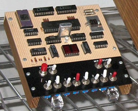
Before I go further, here's a look at an early step in implementing my idea:
An 1802 CPU on a breadboard connected to a Propeller Quickstart board for power and clock.
A first step: Power and Clock from the QS Board to the 1802. (Click for bigger image.)

Here I've gotten to the point of getting clock and two levels of power from the Quickstart board to the 1802 CPU. First, I had a crystal oscillator circuit providing a clock to the 1802. Only 5V power came from the Vin on the Quickstart board.

Then, I split the voltages. The crystal oscillator, the inverter for the clock signal, and Vdd for the 1802 were split off with 5V power, and the rest of the circuit was put on the 3.3V power from the Quickstart board. At this point, I'd been running the 1802 at 1MHz, slow enough I could easily watch the LEDs on the address lines changing as it ran.

Then I moved up to a 2MHz oscillator. The 1802 was still good with that, with its Vdd at 5V and Vcc at 3.3V.

Then I tried to get fancy.

I took an output off the Prop and tried to use a repeat-wait structure to clock the 1802. It worked, up to a point. But I got to where I was unsure of my actual frequency, and the 1802 stopped running at a slower speed than I expected (I thought.) In fact, I was getting too clever and messing myself up. Looking back, I was probably somewhere above 4MHz when the 1802 refused to run any more!

After a while I realized that, and just decided to put the crystal oscillator back in.

Then I took another look, and decided that a 5MHz XI off of the QS board could be used as a clock base. A 2.5MHz clock would be fine (actually, anything from 1.76MHz on up would be fine.) Most Elf computers run somewhere around 1.76 to 1.79MHz to accommodate the clock for the video IC they use. Getting at least that speed is pretty much a must for me to feel like this project is going where I want it to. But getting a faster clock would be even better, as we'll see.

First I dropped in a CMOS part--a 4013--to act as a divider for the 5MHz clock to drop it to 2.5MHz for the 1802. I forgot that at 5V the 4013 only really works up to 4MHz on its input. So that turned out to be a waste of time.

Then I dug out a small supply of 74AC74 ICs, which work fine at well 5MHz and above. It worked fine, dividing the 5MHz down to 2.5MHz. In fact, just to be a little conservative, I used both flip flops to divide the clock down to 1.25MHz, then ran that to the inverter I'd had the crystal oscillator going to.

That worked, so I tried the 2.5MHz output. At first the 1802 wouldn't run, I pushed the Reset switch, and noticed the clock took off when I bumped the Ground wire. Once the ground wire was back in its place securely, the 1802 ran just fine at 2.5MHz.

Then I bypassed the 4049 inverter, the signal from the 74AC74 is plenty strong enough to drive the 1802 by itself.

That was step one. Time for a break before step two.

The Plan
So why hook up an old CPU to a fast modern CPU like the Propeller?

Because of a problem with getting chips for the old Elf computer.

People still like building the old Elf computer. It's a complete computer system that can be built in an afternoon if you've got all the parts and tools at hand (I built my first in about four hours.) It's a computer that pretty well exposes all of its parts to examination, so it's easy to learn how it works, and to understand all the bits of the system.

The video IC, called the CDP1861 Pixie chip, is one of the simplest video ICs ever made. It's basically some timing and control signals wrapped around a shift register that works with the DMA mode of the 1802 to produce a really nifty one chip video interface.

It's not exactly workstation graphics, being monochrome with resolutions ranging from 64 x 32 to 64 x 128. But it does the job. People program the system using this quality of video. And you thought the Vic-20 was low-res!

Well, the problem is that in the past few years Pixie chips have pretty well become Unobtanium (a term that goes way back before the movie Avatar, by the way.) In other words, you can't get 'em. There have been a couple of less than optimal replacements (from the perspective of new ELf builders who have to make them up themselves rather than just buy one pre-made.)

I'm trying to come up with something slightly less suboptimal. And solve a problem that the Pixie chip has.


The Third Cycle...of DOOM

The Pixie's problem is that its timing only deals well with 1802 programs that use instructions that take two instruction cycles or less to complete. There are two instructions, Long Branch and Long Skip, that take 3 cycles. They create jitter in the video by throwing its timing off.

Since the Elf's video is basically just a straight bitmap of a chunk of memory on the screen (the lowest resolution, 64 x 32, is a map of the Elf's base 256 Bytes of memory straight to video.) So, if some other circuit could just read a relatively new, fast RAM in the time when the 1802 isn't reading it, then the other circuit could just pull the data then run it to video, and leave the Elf none the wiser.

That way all the Elf has to do is manipulate the data in the section of memory on the screen. And a 3-cycle instruction won't cause any problems. And the 1802 gets about 40% of its time back, during which it would otherwise have been doing DMA of that memory data to the Pixie chip's shift register.

So:
Video that doesn't need the unobtainable Pixie,
No 3-cycle instruction timing issues,
No loss of 40% processing time to video DMA, and
Able to run at higher clock speeds.

Sounds like a winner, right?

Implementation Details

Next was how to actually implement it. I've looked at several ways, with various advantages and disadvantages.

Using faster RAMs was a first building block I looked at. For example, a static RAM pulled out of a 486 motherboard's cache RAM would be more than fast enough. Both 20nS and 15nS are readily available. Plenty fast to grab a byte once every 1802 instruction cycle for the external video system.

Then, came my initial thought, maybe use an Atmel AVR microcontroller to do the grabbing, put the data into its internal RAM, use that as a frame buffer for some bit-bashed monochrome video. No big deal.

No big deal if you've already got the ability to program AVRs or are prepared to supply them preprogrammed. Still, not a bad solution. Just not likely to be popular as I'd like because of the hurdle of programming the chip. The idea wasn't just considered with an AVR, any of a number of uC families could work. But they had the same problem.

Another idea was to build a circuit from random logic. Not as appealing, with my schedule, but if I could be the pioneer on this and put something together then anyone could order the parts and start wiring. It would probably add about 1/3 to double the work to assembling an Elf computer. Again, not perfect, but possible.

Then I thought about taking the AVR idea and putting in a Propeller board. The advantage here is that, rather than getting a bare microcontroller and having to get the infrastructure to program it to do the One Job that that user may ever use it for, the board itself is all the infrastructure needed. (Yes, Arduino occurred to me, too.)

A download on a computer, a USB cable of the correct type (I'm using a cell phone charging cable), and you're in business. Even if the user never does anything with a Propeller again (what an unfortunate thought!) then they wouldn't be out anything but a bit of their time to get the "part" they need programmed for the job.

And it's less time than hand-wiring random logic on a perf board, no matter how you look at it.


It Just Keeps Getting Better

So, I started with the idea that the speedy (80MHz) Propeller would have no problem sneaking in and reading bytes out of the Elf's RAM during those long, lazy ~200nS slack periods. Then it could put the data into an internal frame buffer.

And, what hey!, the Propeller has built-in video. I could make it so that the final Propellor program puts out Composite baseband, Composite broadcast, and VGA all at once. What a deal! The user doesn't even have to pick between different programs based on what sort of video they want right now.

Then came the next idea. Replace a chunk of the Elf's RAM entirely. Let the Propeller be a chunk of RAM.

It can't replace all the possible RAM of an Elf in its present version. It's only got 32K of RAM in it, and it needs some of that for any applications it's running.

But, it can replace a chunk of the Elf's RAM. Enough for Pixie-quality video. And with some lines used for control, the video resolution and frame buffer location within that memory can be changed. I don't know yet, but it seems like mapping somewhere from 2K to 4K wouldn't be that difficult.


Pixie Compatibility

At first, I'm going to concentrate on a limited memory map, and on replicating the basic Pixie mode of 64 across by 32 high. In spite of the fact that there won't be any actual DMA transfer needed, it should be able to display video from the basic Pixie video programs like the iconic Starship Enterprise video from 1977 without modification. They'll just run faster as a result of no DMA overhead. I think.

Then looking at the exact details of how an expanded Elf uses the other modes (if it does, I've never done so myself) will let me look at expanding the Propeller's memory map area and responding to the Elf's control to do that.

So, if I can do what the Pixie does without requiring DMA, I'm already getting a system that's about 40% faster even if I don't move up the clock speed from ~1.79MHz. (The 1802 was the original overclocker's chip, way back in the 70's, but that's another story.) If I can increase the clock speed even more, with no effect on the video (since a hard-clocked Pixie chip isn't there any more), then I've got a system that'll run such things as Chip-8 and Tiny Basic that much faster than an original Elf with a Pixie.

If the 2.5MHz setup turns out to work (I see no obstacles at present, but that just means I haven't run into them yet), then I'm getting a system that should run about 2.3x faster than the stock Elf. It'll still be no speed demon (that's not the point), but it'll be nicer to use.

Next Steps, Baby Steps

I'm going to write a program for the Prop to make it pretend to be a RAM for the 1802. It will be a simple 256 byte memory. That avoids the multiplexed signals for the address. It'll (hopefully) receive and store data bytes from the 1802, and deliver data from its store on request.

The first pass is going to be really, really simple. I'm going to set up an array, put in a short program to blink an LED on the 1802's 'Q' output, and set it up to respond to the 1802's memory read requests. No writes required. If that works, then I'll add write capability and put in a program to test that (again using Q as an output.)

If that works, I'll proceed to give the 1802 some more sophisticated output and input capability and see where it goes from there. But best not to plan in too detailed a fashion too far ahead until the immediate problems are solved.

Tuesday, July 10, 2012

Gadget Gangster QuickVGA+ for Parallax Propellor

Gadget Gangster QuickVGA+ board for the Parallax Propeller Quickstart Board
Propeller Quickstart Add-Ons Galore

I mentioned that I picked up a Parallax Propeller Quickstart Board a while ago, and finally got around to playing with it.

Well, I've played with it a lot more now, in part thanks to a cool add-on board from an outfit called Gadget Gangster. I bought a Quickstart VGA+ board from them. It adds a nice VGA port (duh) as well a a PS/2 keyboard port (that's PS/2 as in the old IBM "Personal System/2", not Playstation 2), a stereo audio output, and a Wii Nunchuck port (or the classic controller can go here.) All on one little business card sized board, that fits right on top of the Parallax Quickstart board.

It's a nice combination of features. It's also got places for adding an SD card connector (which I've done), an IR port, and a composite video port.

There's a Pocket Mini Computer project built around this board, that's sort of a C-64 retro-clone kind of system. I look forward to trying that out some time when I get tired of playing with the Wii nunchuck as a raw sensor in software.

One note about that...

The nunchuck software that Gadget Gangster recommended didn't work right out of the box. I've posted na updated version of the nunchuck demo software at the Parallax Propeller Object Exchange, the place where Propeller users post their software for others to modify and use. I modified the demo to use the correct I/O lines for the QuickVGA+ board, and I added a bit of code to make it more clear what's going on with the accelerometers in the nunchuck.

Next, I'll be building up my Gadget Gangster QuickProto board, which came in a bundle deal with a QuickStart board (so, yes, I now have two Quickstart boards. And I ordered one for my daughter, too.

Pennies from Heaven
That's not all the Propellers running around the house, as it happens. While we were at the Parallax Robot Expo, my daughter and I picked up some stuff off the Free table. Among those items were a pair of slightly used Propeller Proto USB boards and one one-off PCB Propeller board that appears to mainly for servos. My daughter has one of the Proto boards and I have the other, as well as the one-off PCB.

I've already added PS/2 mouse and keyboard ports to my Prop Proto board, as well as a composite audio/video adapter. I have plans for this board...

I also found an early rev of the Parallax QuickStart Proto board in my bag of goodies, which I'm planning to use to put a sort of Elf II I/O interface on a Quickstart board. A hex keyboard, a pair of hex displays, some control switches, and hey-ho it's 1977 all over again. :)

Bottom line on the Propeller: It's heaps of fun to play with. Quick and easy. I keep thinking I ought to stop and read the documentation, but it hasn't been necessary, yet.

Thursday, January 5, 2012

New Call Sign, New QSL Card

I'm afraid I didn't care much for the Extra class call sign I got from the sequential call sign assignment. It was AG6HU. Before it was assigned, I saw on AE7Q's site that I was likely to get a call from the range AG6HT through AG6HV. I would have been OK with HT or HV, but I was hoping I wouldn't get HU. The call sign is funky enough with the AG prefix, but with an HU suffix there's just nothing there to love.

I tried, I really did. I tried coming up with interesting phoney phonetics for it ("higher up", "hugely unpopular", "hic up", etc.) What really sealed that call's fate for me was when I tried telling it to people. It took a minimum of three tried to get it across, even when using the International Phonetic Alphabet. That's bad.

So I applied for a vanity call sign. I didn't rush right out, though I didn't dilly-dally, either. Knowing that I wasn't going to stick with AG6HU meant that I wanted to get a new call before establishing much of an identity with that call. I spent a lot of time thinking about what I'd want that'd still be fun to have 20 plus years from now.

Since retrocomputing and microcontrollers are both hobbies of mine, the call W8BIT seemed appropriate. That's what I put at the top of the list, and that's what I got. W6CPU and W6TTY were high on my list. I didn't realize it when I applied, but another ham applied for W6TTY a few days before I did, and got that assigned during the 18 day waiting period for my new call (not that it mattered, since my first choice was available, but an example of a good reason to have more than one choice and be prepared to not get your first choice.)

Another one that would have been a lot of fun is KO5MAC, since I'm a fan of the COSMAC microprocessor (the RCA 1802.) It's a bit more specialized than simply "8BIT", so it ended up as a lower preference. Beyond the first three choices I listed, I didn't worry much about the order of the other calls I put on the list relative to my preferences. Any of them were better than AG6HU, and I pretty well expected that things weren't very likely at all to go past the top three. KO5MAC would probably have been my fourth choice if I had arranged them. It's an awfully fun call sign, just like the 1802 is a really fun chip.

I considered having a call with my current favorite microcontroller referenced, the Atmel AVR, like, say K6AVR or W6AVR (no idea if these are in use or not.) But that seemed potentially even a bit more narrow than the COSMAC reference, especially when viewed from the perspective of 20 years from now.

I got my new call sign on the 4th, I'd already figured out what I wanted to do for my QSL card. I got 100 of them printed up today. Here's what it looks like:

QSL card for W8BIT, lots of 8-bit processors in the background, and one video chip that I mistook for a 6502 processor.


Ready to Go, Almost
On the more practical side of amateur radio--making actual radio contacts--I'm still moving things forward. Yesterday afternoon I replaced the towels stuffed in the window where the antenna cable comes through with a purpose-made wooden feedthrough. It looks a lot less "redneck" than the towels stuffed in a window casement.

Unfortunately, I don't have a good ground to the transceiver in its temporary home yet. I'd hoped to have time to pull that in yesterday but time ran short. But that's next. I'm not too worried about the ground when I'm just listening in, but before I key the mike I want to have a good ground on the radio's chassis. Then I'll be ready to jump into 40 meters, and possibly 15 meters.

I've been listening in a lot on 40 meters over the past week, and I'm starting to get a pretty good feel for the band. Like what frequencies folks are using pretty commonly, what sort of traffic is going on when (daily nets, some of the weekly nets, and so on.) So I'm pretty confident I won't seem to be a complete and total lid when I do key up. Though I'm prepared to make _some_ mistakes, it's part of the learning process.

Then the next major step is to clear out my corner of the garage, put in an AC/heater unit in the wall, a raised floor, and a bit of insulation. A few more touches like a mecca ground plate and feedthrough panel then I'm ready to put in shelves and furniture.

Somewhere in there I want to get or build a decent morse key or keyer. All I have on hand right now are a couple of ones of about the quality that were in kid's science kits 30-40 years ago.

So long as my current antenna keeps me going, I'll just go with it until the new radio shack is done before hanging up a new multiband antenna. A G5RV has been highly recommended to me by at least two hams. I've got a good idea of where a full size one would go on my property, and I'm looking to see if I can fit in a double-size one at right angles, more or less, to the first. That'd (hopefully) get me on the 160m band, too.

Lots to do, lots to do. In the meanwhile I'm going to grab my HT and make some contacts on 2m simplex.

73

Wednesday, November 9, 2011

Low Level Computer Teaching Options

We have a current discussion on the COSMAC Elf Discussion Group that centers on the idea of a small computer to teach low level computer concepts. Many of us in the group got our start with the COSMAC Elf as our first home computer. It is a small, simple, inexpensive computer. One of its finest points is that it is simple enough that a person of ordinary intelligence can understand how every part of it works, down to the lowest detail.

The place for a small teaching computer, as we're discussing it, lies somewhere between electronics and the standard non-computer science introductory computer programming class. It's a matter of teaching what the components in the system do, and how they do it. This becomes a model of what happens inside more powerful modern computers at larger scale. Such as in current desktops, laptops, tablets, and smartphones.

COSMAC Elf single-board computer with PIXIE video. A complete computer system in 1977 with only 13 integrated circuits!
The COSMAC Elf, this version includes video graphics.


Is anyone using something along the lines of a microprocessor trainer in the classroom today outside a college level EE class?

Personally I can see two general approaches to this, with several possible variations on the two themes. Let's look at them, then I'll go into Blue Sky mode to talk about what I sort of wish for.

Some Ways to Bring Computer Hardware into Class
One is to fake it entirely with present-day hardware. After all, if it's possible to do a complete chip-level simulation of an 8-bit processor in Javascript, it shouldn't be much of a stretch to simulate an entire simple 8-bit microcomputer in a program with the ability to "see" all the operations inside simulated on the screen.

The problem is that this still really fails to make what's being taught "real". To the students, it becomes just another show to watch--one with no particular interest to most of them.

The other approach is to use an actual old microcomputer in class, like the Elf, with the students handling the system, measuring voltages or using logic probes to "see" the signals in the computer. Something more sophisticated would be using chip clips with LEDs on the various lines as a sort of multi-line logic probe. (Here is a place where an Elf or other RCA1802-based system would shine. The 1802 is a fully static processor. It can run at clocks speeds from 0Hz on up to its maximum clock speed, with clock changes on the fly. I have literally clocked 1802 systems by hand by connecting and disconnecting the clock line to +5V and Ground lines, counting out machine cycles as displays show the status of various system lines. There are not a lot of computer systems that can do that!)

An annotated image of a COSMAC Elf computer, showing the location of CPU, memory, and other ICs.


Between these two lie many other options. One would be to have a hardware board that connects to a modern computer through a common interface, like USB, where some I/O devices could be visible controlled by the computer (via lights, motors, etc.) and with lines exposed that can safely be probed by the students.

Another would be using a more modern hardware platform, perhaps based on one or more microcontrollers that emulate the function of an older system, exposing such things as memory access, control signals, and so on to the students. The board could include displays and LEDs to show the status of the lines, internal pseudo-registers, and so on. The operation of the entire system, both inside and outside the simulated ICs, could be made available to the student's eyes.

Part of what needs definition is the acceptable limitations of the system. In my own case, I see such a system as being an introduction to low-level hardware operation and control of that operation through software.

Blue Sky Dreaming
If I could have what I wanted without any effort on my part or a significant amount of the school's money, here's what I'd like:

Step 1
I would want to introduce a basic system that's very similar to the original Elf of 1976.

It would have:
  • Toggle switch inputs (to associate signals with data and to help teach binary),

  • A binary LED display and a two-digit hexadecimal display,

  • Very limited memory (about 128 to 256 bytes)(to teach how much can be done in limited memory, and to limit the size of early programs to sane sizes.

  • Exposed memory and I/O lines, possibly with LED monitors

  • Extra monitors, like maybe dual color LEDs to show data direction on I/O ports, etc.

  • A simple machine language with whole-word mnemonics.

  • The ability to operate at extremely low clock speeds (0-100Hz) as well as higher speeds (1-10MHz or something like.)


Step 2
  • Hexadecimal Keyboard

  • 512B to 1024B of RAM

After the first few lessons, the toggle switches would get old and I'd want to introduce a hexadecimal keypad. This would teach hexadecimal, and continue the association of computer instructions with numeric values in the computer. Presumably the connection between signal levels and numbers has been made using toggle switches.

With the easier input technique, it'd be nice to add some more memory, up to something like 512 bytes to 1 kilobyte.

Step 3
  • Keyboard with instruction mnemonics and hex digits

  • Perhaps more memory, up to about 4K

Next, a keyboard would be attached. Perhaps writing software to interface the keyboard to the system would be one of the Step 2 projects. While I'd be tempted to use an ASCII keyboard, I think a raw matrix keyboard would teach more. On this keyboard, machine language instructions and hexadecimal numbers would be mapped to each key. This would again speed programming, and reduce errors. The simple machine language I envision has a particular addressing mode associated with each mnemonic, so there's still no assembling of code required.

Step 4: A larger step
Next, I'd move to a more abstract level. I believe that the activities prior to this point would teach low level operations well enough to take this jump and still be able to show the connection between the two.

For step 4, the computer would get:

  • More memory. Anywhere from 4K to 64K. Perhaps it would start at 4K and grow as the students hit the limitations of each memory size.

  • A terminal connection to a current generation computer for keyboard and display, or an encoded keyboard and some other form of text display.

  • New firmware (probably activated from on-board with a mode switch), which would provide a fairly sophisticated command line interface with command editing, recall, etc., as well as an interactive programming language. The specific language doesn't matter too much, it could be a BASIC, a bash-alike, a LOGO, or an interactive form of some other compiled language.

  • Mass storage. Probably some modern semiconductor memory.


The point at this step would be writing high level programs to perform low level actions like those seen in the earlier steps. Seeing line levels and I/O operations performed, using bitwise operators, seeing the signals represented as numbers of various bases within the language (which I'd expect to support at least binary, hex, and decimal for representation and constants.)

Step 5
The final step with the low level computer would be to produce more sophisticated programs. These would be longer programs, probably projects done by groups of students over a few weeks in class. At this point the understanding of the program control structures and data structures should be a bridge to programming in the chosen language directly on the modern computer.

Final Thoughts
These thoughts are somewhat half-baked as they stand. I or someone would have to do some more work to really define this and turn it into hardware and software and a curriculum to go with it. Some points that need considering are the demarcation between this and a robotics class, common in many schools now (including the one at which I teach.) Also, how much class time does this merit? And so on.

Personally I think that using a micro trainer level system is simple enough to be mastered by most middle-school level students. I've got some actual experience with students to back that up, in addition to my own experience (I was 14 when I constructed my own Elf.) For the students, the information not only gives them an understanding of the underlying technologies of current systems, but would open the doors to embedded systems, far more common than conventional general purpose computers. Either way, it would make the computer far less a piece of technical magic controlled by somebody else and far more something comprehensible, and therefore controllable, by themselves.

Some related work--a 4 bit TTL Processor.

The fact is, all the steps above would probably be unnecessary and involve too many changes to the hardware platform to be practical in class. A more reasonable approach would probably be to go from a slightly more capable Step 1 computer directly to Step 4. This would reduce the opportunity for student disorientation as a result of seemingly constant hardware changes, and still be enough to get the key points across.

The activities I envision for Steps 2 and 3 could be either dropped or performed in either the initial or final configuration of the system. This would also simplify the system itself.

Saturday, December 4, 2010

Retrocomputing for the Holidays

What could be better than an old computer under the Christmas tree? It's a fun, inexpensive gift. There's always something old under out Christmas tree. Among the larger items have been the Commodore 64 that I gave my daughters as their first computer ten years ago. It included a monitor and floppy drive, of course, and copies of the user's manual and programmer's guide.

They'd both already started programming in BASIC on my Apple IIe during the prior year. So they were ready for the C-64! I got myself a Softcard for my Apple IIe that same year.

Two years later, I added a Plus/4, since they were frustrated with the lack of direct graphics commands on the C-64. Peek and poke wasn't good enough. ;) That same year some friends gave me their Laser 128 (Apple IIc clone.)

Christmas Cheer with PA-RISC

Another two years pass, and they both got an HP9000/700 series Unix workstation. They spent Christmas break learning Bourne shell and playing with Neko under X-Windows. Yeah, these weren't 8-bitters, but they were fun old systems that ran plenty of network apps. I had a MUD on my Unix workstation, and they learned how to telnet in and play pretty quickly. Their typing improved dramatically.

I picked up an Amiga 500 and that became the family's Christmas present the next year. We hooked it up to our 36" TV and played music, games, and a bunch of demos.

The year after that, a friend gave me a Bigboard I system. CP/M, 64K, and two big 8" floppy drives. Wordstar and BASIC-80 heaven. Everyone gathered around to roast chestnuts over the power supply and listen to the disk drives churn. ;)


Sure, it's got iTunes. Does it do X-Windows?
That same year, my daughters got upgraded to Macs, G3 B&Ws. They were excited about getting a computer that would run iTunes, but first they made sure that all their Unix stuff would run as well. Once they were sure they weren't giving up the Unix command line and could port their applications, THEN they were OK with the upgrade.

Three years ago, I did some repairs to a Kaypro 4 to get it working again. Unfortunately I haven't figured out how to read and write standard diskettes with it yet. It's a souped-up unit, with an aftermarket ROM, hard disk, and floppy drives that include both double and high density units. It got set on the back burner in favor of some other projects, once they're finished I'll get back to determining if I've got all the right software to go with the ROM that's in the system.

Visiting Old Friends

Two years ago, I actually avoided adding any new hardware for the year. Instead, I spent time during the holidays pulling out several of the systems I have that have been a bit neglected and giving them some TLC then playing with them. The Apple IIe, my own C-64, another Plus/4, and the Big Board.

Last year was the year of hardware projects. I had a new 8085 computer on a breadboard (see the story at http://saundby.com/), and was preparing to move it to soldered circuit cards. I was also migrating my Ampro Little Board (a Z-80 system) from loose components on the table top to living in a box like a proper computer.

Bringing Up the Ampro Little Board

Catching Up for Christmas

This year I'm working to finish the non-breadboarded version of my 8085 and building up a Membership Card (1802-based computer, similar to a COSMAC Elf from 1976 but a lot smaller) in a decorative little Victorian-style case. I'll be posting that on my web page at saundby.com soon, I expect.

I'm keeping my eyes peeled for a Commodore 128 at the thrift stores, too. That'd really round out this Christmas year.

What's on Your List?
What retrocomputer experiences have you had for Christmases past, and what are you hoping for under the tree this year that's hopelessly "out of date"? :)

Wednesday, June 30, 2010

Retrocomputing Summer

Aside from some astronomy, I've been spending a lot of my free time this summer on some retrocomputing projects. In particular, I've been working on my homebrew 8085 single board computer and my Ampro Little Board Plus Z-80 systems. Alongside that, I've been trying to fit a new computer that's similar to a COSMAC Elf into an Altoids tin.


Lee Hart's 1802-Based Mini-Microcomputer: The Membership Card.


Lee Hart's Membership Card computer. A COSMAC Elf in an Altoids tin...almost.
Retrocomputing in Your Pocket.
Lee Hart's Membership Card computer. It's based on the RCA 1802 microprocessor, and it's a close cousin to the COSMAC Elf computer (Google it, if you don't know about it!)
Lee Hart gave me a set of printed circuit boards for his new Membership Card computer last fall. It's a really neat design. In essence, it's a COSMAC Elf that fits in those handy little enclosures, Altoids tins. It can take up to 32KB of memory, in either a ROM or a RAM, and includes a full front panel with toggle switches and LEDs displaying binary. If you don't want to go quite so hairshirt, you can connect to a PC over a serial port, or build your own front panel card. I'm thinking of going with a hex display and hexadecimal keypad in a future build.

Meanwhile, I'm trying to fit my Membership Card into its tin. I think my switches are too tall, so I'm going to have to make some other accomodations.


Lee Hart's Membership Card. The tin doesn't quite close with the switches I'm using.
The tin doesn't quite close up. My interconnect between the PCBs may be too tall, or my switches aren't laying as low as Lee's did. It's only about 1.5mm, but it's enough. I'm working on Plan B now.


My 8085 Handheld Single Board Computer Project


Rev. 1 of my 8085 computer's front panel, laid out on acrylic sheet.
My first shot at a front panel layout for my 8085 computer, laid out on acrylic sheet to make it easy to see what's where.
I've been working on my new 8085 computer project for a few months now. It's a new-design retrocomputer that's easy to build. I have the project designed so that a builder can put it together a little bit at a time, and test it thoroughly at each stage. That way you don't need to put together a bunch of parts then see if it all works at the end, and then wonder what's wrong when it doesn't all work together.

Each step of the project adds just one to three new pieces to the computer. The complete computer is only twelve integrated circuits, plus resistors, capacitors, and other small parts. It can be built with only eight ICs, if you want a simpler version that gives up a couple of extras. These can always be added in later, if desired. The real key to the project is that it provides a complete, functional 8085 system similar to the SDK-85 development system that can be built up from simple parts that are easy to understand and use in programs.

Most of my work lately, other than playing with software and deciding how I want the programmer's interface to work in its operating system, has been on the front panel of the computer and its enclosure. I want it to be something that someone with minimal tools, and even without power tools, can build from common materials available at an ordinary hardware store. I also want it to be attractive enough to show off after it's built, not something that looks like it belongs in a junkpile.


The 8085's new Masonite (hardboard) face panel, partially complete in this image.
The partially-complete Masonite face panel of my 8085 computer.
I've nearly finished the third and final version of the face panel. I learned some things while making the first two that made me keep trying again. Fortunately, nobody else will have to go through three tries to get it right. I'll soon be posting the instructions for constructing the nice version of the front panel, and the enclosure, on my website. After trying acrylic and metal, I decided to go with Masonite (hardboard) as a material that anyone should be able to work and that can be made to look professional, even with hand tools. Masonite is an old friend of mine, I've been building enclosures out of it since the 60's, when I had nothing but unpowered hand tools, and very few of those, to work with (Back then I cut my panels with steak knives!)

Since posting details on the 8085 construction project takes about 3 times as long as doing it, I've been holding off on doing an update of the project on its site until I have the enclosure complete. Now I'm almost done, so an update will probably occupy the later part of my summer.


Ampro Little Board Plus Z-80


Ampro Little Board Plus on my kitchen table during initial fire-up.
My Ampro Little Board Plus, in its original incarnation. A pile of parts on a kitchen table.
I first constructed my Ampro system as a mass of loose parts and cables on my kitchen table. The Ampro is a single board computer based on the Z-80 processor that includes serial and parallel I/O, 64K of memory, and a SCSI controller all on a board that's sized to piggyback on a 5-1/4" floppy disk drive. They were the original "bookshelf" computer, long before today's Mini and Micro-ETX systems appeared.

I got a pair of system boards for these from Dave Baldwin when he was cleaning out some old computers prior to a move. One night, I really wanted to get one of the many systems up and running that Dave had given me, and since these seemed like they'd be the easiest to get running I grabbed one and got it going.


The Ampro Little Board Plus Z-80 PCB
A complete computer, with Z-80 CPU at 4MHz, Floppy Disk Drive Controller, Serial and Parallel I/O, and SCSI all on one small card--in 1984!
Since then, I've been using it as a pretty maxed-out CP/M system. I put a 2GB SCSI hard disk on it, of which I'm only actually using 88MB (which is plenty, I never filled the 10MB of disk space on my old Kaypro 10 CP/M system, after all.) First, I played with it using just CP/M and its utilities. Since then, I've installed a couple of development systems--Turbo Pascal 3.02 and Workman's FTL Modula-2--as well as WordStar 3.0.


The Ampro LB+, covering my dinner table.
Honey, how about we eat dinner on the patio tonight?
I did move it off the dinner table! It's been living on an "occasional table" in our living room for the past several months (occasional tables seem to happen more than occasionally in our house.) I've been wanting to move it into my computer room in the house. But there wasn't room on my desk.

Then Vic Maris of StellarVue Telescopes offered me an old desk he didn't need at his offices any more. He said it was large. It is. I had to do some major work to get it into my office. But once there, I put my usual computers on it (an iMac 20" and a Beige G3 PowerPC Mac), and had enough room for one more computer!


My PowerPC Mac, iMac, and the Ampro's terminal all happily living together on my new desk.
My new desk, with Three full size computers.

I put the Ampro's current box (a PC's beige box) under the desk. I've got another enclosure for it that'll be much more attractive and interesting--but that's another project yet to come. On top, I had plenty of room for my ADDS 2020 terminal, which is the user interface for the Ampro. Unlike the original Big Board computer (the "Ferguson"), the Ampro uses a terminal, whereas the Big Board has a built in CRT and keyboard interface.

Once I got everything in place, I started working with my ADDS terminal to try to get the best image out of it. I originally used this terminal with the Ampro because it's the smallest full terminal I've got. I took a look at all the space on my new desk, and realized...I could use a better terminal. So I pulled out my VT-102, which has a very nice white on black character display and is very sharp.


The new desk with the Beige G3, aluminum iMac, and VT-102 on it.
The Beige G3 runs Lemmings and Warcraft, the iMac is my interwebs machine, it's desktop background is an image of the Big Board computer PCB, and to the right is my Ampro's terminal, here showing the utilities menu.

The VT-102 wasn't perfect, though. So, thanks to some help from fellow retrocomputerists I was able to find the technical info I needed to adjust the character height on the display (it was a little taller in one part than another when it came out of the garage.) Now it's perfect.

Now I'm happily writing games in Turbo Pascal at my desk, and the space next to my easy chair is waiting for another project to move in while my wife's back is turned.


The mess of displaced stuff from the desk swap.
Getting the new desk in meant moving some stuff out.
Here is my electronic workbench, covered in clutter. You can see my breadboard 8085 on the left, the new 8085 on the bench, with the face panel parts on top of the oscilloscope. The computer system is a 486 that I still use for burning ROMs and transferring data between newer systems and older ones. In front on the desk is the plastic tub that holds the Membership Card's parts. Doesn't everyone have a beef jerky jar filled with capacitors on their desk? Mine is on the right, with the blue and red things in it that aren't candy. On top of and beside the monitor are my three STK-500 development boards for my AVR projects. I have three so that I can have each set up for a different chip at the same time.

Since this picture was taken I've cleaned up. Really.

The breadboard version of my 8085 computer, the MAG-85 is still in use, by the way. That's where I've been doing my OS development while I finish the permanent version of the hardware. That way I don't have to worry if I've got the permanent one's keyboard and display off for work on the face panel if I want to sit down and code some 8080/8085 assembly.